
Digital Thermometer Circuit

The PIC16F84A microcontroller serves as the core processing unit of the digital thermometer circuit. It is equipped with an 8-bit architecture and supports a range of peripherals, making it suitable for various applications, including temperature measurement. The circuit typically incorporates a temperature sensor, such as an LM35 or a thermistor, which converts temperature variations into corresponding electrical signals.
In this configuration, the temperature sensor outputs an analog voltage that is proportional to the ambient temperature. This analog signal is then fed into one of the analog-to-digital converter (ADC) channels of the PIC16F84A. The microcontroller processes this signal, converting it into a digital value that represents the temperature in degrees Celsius or Fahrenheit.
Additional components in the circuit may include resistors, capacitors, and possibly an operational amplifier to condition the sensor's output signal for optimal ADC performance. A display unit, such as a 7-segment LED display or an LCD, is often incorporated to visually present the temperature readings. The microcontroller controls the display, refreshing it at regular intervals to provide real-time temperature data.
Power supply considerations are also crucial; the circuit typically operates on a regulated voltage source, often 5V, to ensure stable performance. Proper decoupling capacitors should be placed near the power pins of the microcontroller to filter out noise and maintain a reliable operation.
Overall, the PIC16F84A digital thermometer circuit represents an efficient and effective approach to temperature measurement, leveraging the capabilities of the microcontroller and discrete components to deliver accurate readings.PIC16F84A Digital Thermometer Circuit The digital thermometer circuit is built, almost all by using the temperature sensor of some form of discrete components,. 🔗 External reference
Related Circuits
A relay (RL1) is activated with a 100-second delay when a +12V power supply is connected to the circuit. Figure 2 illustrates a relay timer circuit utilizing a 555 timer, featuring two time ranges: 6-60 seconds and 1-10 minutes...
This timer is designed for individuals seeking to achieve a tan while minimizing excessive exposure to sunlight. A rotary switch allows the user to set the timer based on six classified photo-types. A photoresistor adjusts the preset time value...
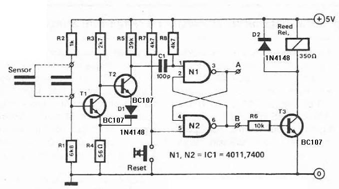
This humidity detector circuit diagram is straightforward and utilizes a limited number of components. It can be employed to activate electronic devices when the detector identifies a specific humidity level. The sensor is made from two copper pieces positioned...

This cool-down relay circuit utilizes an integrated circuit (IC) timer to control a relay, which maintains the operation of the blower for a specified time delay determined by timer U3. The capacitance value of C2 can be adjusted to...
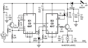
The following circuit illustrates an Infrared Toy Car Motor Controller Circuit Diagram. This circuit is based on the 4017 IC. Features: operating at .. The Infrared Toy Car Motor Controller Circuit utilizes a 4017 Decade Counter IC, which is integral...
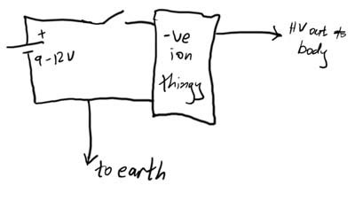
This article demonstrates how to create a simple yet effective static electricity generator. This device enables the user to carry a constant static charge on their body and discharge it onto anything grounded or of opposite polarity. The generated...