
Precise wave generator
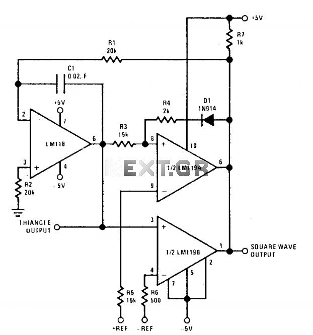
The described circuit is a versatile oscillator capable of generating a triangle wave with finely tunable parameters. The integration stage is responsible for producing a linear ramp voltage, which is then fed into two comparators. These comparators are critical for defining the waveform's peaks. The first comparator is set to trigger at the positive peak voltage, while the second comparator triggers at the negative peak, thus establishing the amplitude of the output waveform.
The ability to control the peak amplitudes with high precision is essential for applications requiring specific voltage levels. The use of a DC input for amplitude control ensures that the adjustments can be made without introducing significant noise or instability into the circuit. The integration time, which directly influences the frequency of the output waveform, can be finely tuned by replacing R1 with a potentiometer. This substitution allows for a broad frequency range while maintaining the desired amplitude, making the circuit adaptable for various applications.
Furthermore, the symmetry of the triangle wave can be adjusted by connecting a resistor from the inverting input of the LM118 to the potentiometer. This configuration enables the user to modify the duty cycle of the output waveform, which is particularly useful in signal processing and modulation applications. The connection of the potentiometer across the power supplies ensures that the adjustments made to the ramp time do not affect the overall stability of the circuit.
In summary, this oscillator design combines precision amplitude control, adjustable frequency, and symmetry, making it suitable for a wide array of electronic applications, from waveform generation to signal conditioning. The careful selection of components and the design of the feedback network provide a robust platform for generating stable and reliable triangle wave signals.The positive and negative peak amplitude is controllable to an accuracy of about ± 0.01 V by a dc input. Also, the output frequency and symmetry are easily adjustable. The oscillator consists of an integrator and two comparators—one comparator sets the positive peak and the other the negative peak of the triangle wave.
If R1 is replaced by a potentiometer, the frequency can be varied over at least a 10 to 1 range without affecting amplitude. Symmetry is also adjustable by connecting a 50 kfi resistor from the inverting input of the LM118 to the arm of the 1 kO potentiometer.
The ends of the potentiometer are connected across the supplies. Current for the resistor either adds or subtracts from the current through Rl, changing the ramp time. 🔗 External reference
Related Circuits
This circuit is a melody generator circuit diagram controlled by the UM66 IC. The UM66 is a CMOS IC designed for applications such as call bells, telephones, and toys. It features a built-in ROM programmed to play music and...

To achieve optimal performance from an NBTV signal, it is crucial to utilize the complete dynamic range of the signal without any crushing at the black level or peak white. To evaluate the linearity of a video path, it...
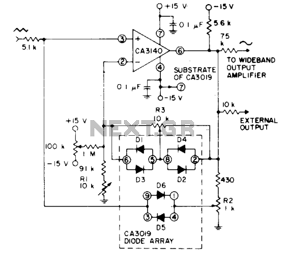
Utilizes a CA3140 BiMOS operational amplifier configured as a voltage follower, along with diodes from a CA3019 array, to transform a triangular signal (such as that produced by a function generator) into a sine-wave output with a typical total...

In this circuit, an additional exclusive-OR gate is connected after the modulo-2 feedback, with CI and R2 applying the supply turn-on ramp into the feedback loop. This provides sufficient transient signal so that the PRBS generator can self-start during...
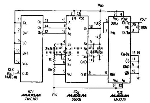
A TTL counter, an 8-channel analog multiplexer, and a fourth-order low-pass filter can generate sine waves ranging from 10 kHz to 25 kHz with a total harmonic distortion (THD) better than -80 dB. The circuit employs two cascaded second-order,...
The 555 Stepper Pulse Generator kit provides the necessary pulse signals to drive various DC servo motor applications. The 555 Stepper Pulse Generator is a versatile electronic circuit designed to generate precise pulse signals essential for controlling DC servo motors....