
Stepper Motor Speed And Direction Controller
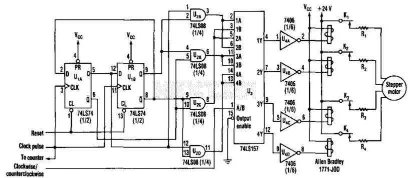
The circuit consists of four primary components: flip-flops, AND gates, a clock pulse generator, and a motor driver stage. The flip-flops serve as memory elements, maintaining the state of the motor control logic. The AND gates are used to process the signals coming from the flip-flops, enabling precise control over the motor operation based on the desired speed.
The clock pulse generator is a crucial element in this design, as it establishes the timing for the entire circuit. By adjusting the frequency of the clock pulses, the user can effectively change the RPM of the stepper motor. This allows for fine-tuned control over the motor's performance, making it suitable for applications requiring variable speed.
Incorporating switching transistors instead of traditional solid-state relays improves the circuit's efficiency. Transistors can switch on and off more rapidly than relays, resulting in faster response times and lower power consumption. This enhancement is particularly beneficial in applications where the motor speed must be adjusted frequently.
The use of standard SSI LSTTL chips ensures compatibility and ease of integration with other components in electronic systems. These chips provide reliable performance and are widely available, making them a practical choice for this circuit design.
Overall, the circuit represents a robust solution for controlling stepper motors, combining flexibility in design with enhanced operational efficiency. This new circuit uses four chips, with an option of using just three (the flip-flops and AND g ates can be combined). The rate of clock pulses determines the motor"s rpm. Switching transistors can replace the relays to increase the circuit"s efficiency. This circuit drives a stepper motor whose speed depends on clock rate. Standard SSI LSTTL chips are used. Switching transistors can be used in place of the solid-state relays to improve the circuit"s efficiency. 🔗 External reference
Related Circuits
A pulse width modulator (PWM) is a device that may be used as an efficient light dimmer or DC motor speed controller. The circuit described here is for a general purpose device that can control DC devices which draw...
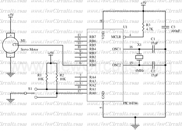
This simple micro-control circuit controls a servo motor according to a 3-state switch. A servo motor acts as an actuator in 3 positions. It has 3 wires, one for VCC, one for Ground, and another one for position control....
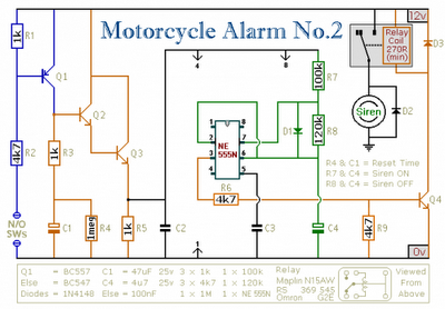
Any number of normally-open switches may be utilized. Install "tilt" switches that close when the steering is moved or when the bike is lifted off its side-stand or pushed forward off its centre-stand. Employ micro-switches to secure removable panels...
This is a Class D audio amplifier circuit used to control the PWM motor speed. This circuit has two advantages for battery-powered portable devices. First, it provides high efficiency, which extends battery life. The Class D audio amplifier operates by...
Car and Motorcycle Battery Tester Circuit. Going camping today often requires bringing various electronic devices for daily activities or entertainment. Typically, a charged lead-acid battery and a power source are essential. The Car and Motorcycle Battery Tester Circuit is designed...
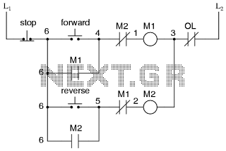
This is the power diagram for motor forward and reverse operation. To change the motor direction, one polarity must be altered, for example, changing R to S. For detailed information, please refer to the following. The described power diagram illustrates...