
Stereo Audio Power Meter
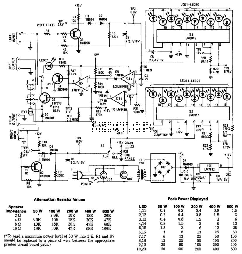
The audio power metering circuit operates by monitoring the output power of an amplifier and ensuring that the connected speaker does not exceed its power rating. The inclusion of relay RY1 acts as a protective mechanism, disconnecting the speaker when the power output surpasses safe levels. The circuit is capable of handling stereo applications by utilizing two channels, allowing for simultaneous monitoring of both left and right audio outputs.
The attenuator formed by resistors R1, R2, and R3 reduces the signal level to a manageable range for the subsequent components. Capacitor C1 plays a crucial role in voltage detection; it stores charge and allows the comparator IC3A to respond to the voltage level that indicates a potential overload. When the voltage across C1 reaches a predetermined level, IC3A outputs a high signal, which activates the drive circuit composed of IC4 and Q4. This stage amplifies the signal to trigger transistor Q3, which operates relay RY1.
The illumination of LED21 serves as a visual indicator of the relay's activation, providing immediate feedback that the speakers have been disconnected due to excess power. Meanwhile, IC1 continuously monitors the voltage across C1 and drives a bar-graph display consisting of ten LEDs (LED1 to LED10). This visual representation allows users to easily gauge the power output level, enhancing usability and providing clear feedback on the amplifier's performance.
For applications requiring a maximum power measurement of 50W into a 2-ohm load, the circuit design specifies replacing resistors R1 and R7 with a wire. This modification ensures that the signal path is optimized for higher power levels, allowing for accurate readings without attenuation. Overall, this circuit is a robust solution for monitoring audio power output, protecting speakers, and providing visual feedback to users. This circuit is used to meter the audio power output of an amplifier feeding a speaker. RY1 is actuated if excess power is fed to the speaker. Two channels are included for stereo applications. R1 and R2 and R3 form an attenuator. When a signal level is reached that produces a voltage across CI, comparator IC3A goes high, and IC4 and Q4 produce enough drive to Q3 to trip relay 1, which cuts off the speakers. LED21 will light as well. In addition, IC1 reads the voltage across CI. IC1 is a bar-graph driver, which lights bar-graph display LED1 through LED10. To read a maximum power level of 50W into 2ohm, R1 and R7 should be replaced by a piece of wire between the appropriate printed circuit board pads.
🔗 External reference
Related Circuits
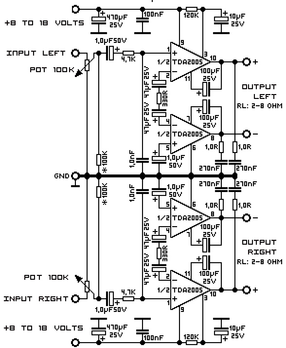
A 20W TDA2005 stereo amplifier designed for various applications, including the amplification of medium power speakers. It is suitable for automotive use; however, the power supply must be equipped with a choke of at least 150mH and should provide...

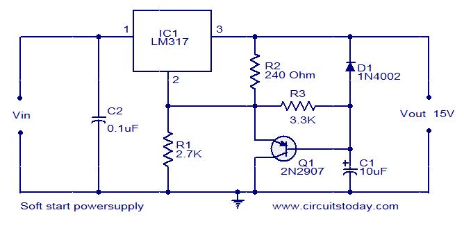
This project involved the design of an audio amplifier that delivers substantial output power while maintaining a minimal parts count and high quality. The power amplifier section utilizes only three transistors along with a few resistors and capacitors arranged...
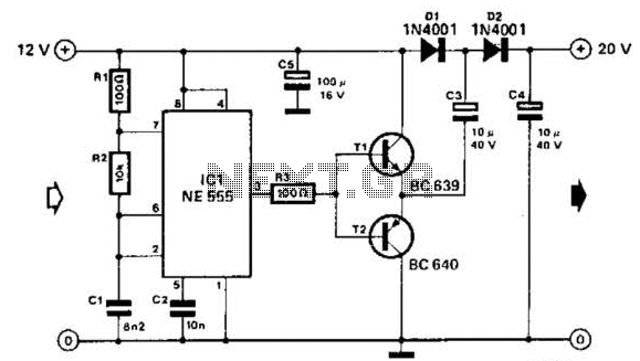
Using a 555 timer and voltage doubler, this circuit will supply over 50 mA at 20 V DC. Transistors T1 and T2 act as power amplifiers to drive the voltage doubler. The frequency of operation is approximately 8.5 kHz. The...
This post presents an interesting topic about switching power supply circuit diagrams for those who wish to learn more. A switching power supply is a type of power supply that uses a switching regulator to convert electrical power efficiently. Unlike...
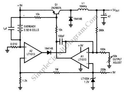
A circuit of a low-power switching regulator is illustrated in the schematic diagram below. This circuit can provide an output voltage of 5V from a 9V source. The efficiency... The low-power switching regulator circuit is designed to convert a higher...
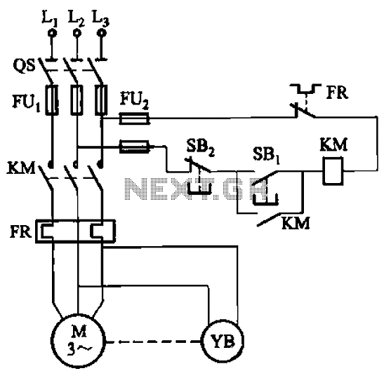
The circuit depicted in Figure 3-121 illustrates the key component of an electromagnetic holding brake, which consists of an electromagnetic brake solenoid primarily made up of two parts: the iron core and the shoe brake components. When power is...