
Stereo balance meter
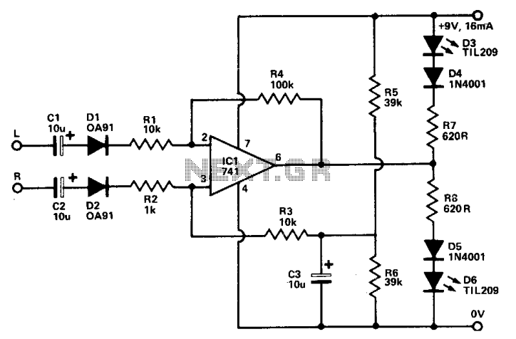
The circuit described involves an amplifier with a built-in indicator system that utilizes LEDs to provide visual feedback on the balance of audio output. When the amplifier is switched to mono mode, it combines the left and right audio channels into a single channel. This mode is essential for adjusting the balance control, which is a variable resistor that alters the relative volume levels of the left and right channels.
In this configuration, the balance control is adjusted to achieve equal illumination of both LEDs, indicating that the audio output is balanced. The LEDs serve as visual indicators, where each LED corresponds to one of the audio channels. When both LEDs shine with equal brightness, the output is perfectly balanced, ensuring that the sound is evenly distributed to the speakers.
The amplifier's circuitry likely includes a microcontroller or a simple comparator circuit that monitors the output levels of each channel. This system can be designed to provide feedback in real-time, allowing for precise adjustments. The use of mono mode simplifies the balance adjustment process by eliminating the complexities of stereo sound, making it easier for users to achieve the desired auditory experience.
Once the balance control is set correctly, the amplifier can be switched back to stereo mode, allowing for a full stereo sound experience with the channels properly balanced. This feature is particularly useful in audio setups where channel imbalances can significantly affect sound quality and listener experience.To use the indicator, switch the amplifier to mono mode and adjust the balance control until both LEDs are equally illuminated. The amplifier is now in perfect stereo mode balance. 🔗 External reference
Related Circuits
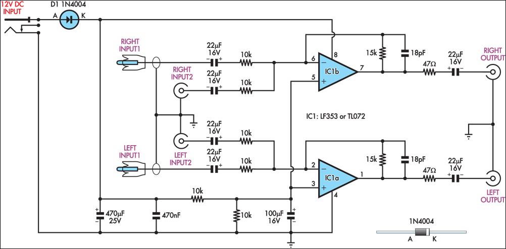
This circuit combines two separate line-level stereo (left and right) signals into a single stereo output, eliminating the need to switch between two sets of input signals. In this application, it is utilized to connect stereo audio from a...
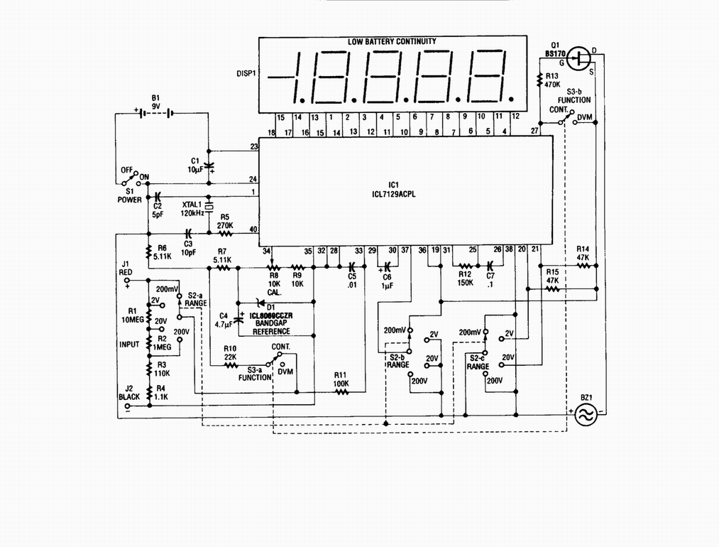
Single-chip digital voltmeter. This 4 1/2-digit DVM circuit is built around a Maxim ICL7129ACPL A/D converter and LCD driver. An ICL8069 CCZR 1.2-V band-gap reference diode is used for accuracy. The described circuit is a single-chip digital voltmeter (DVM) utilizing...
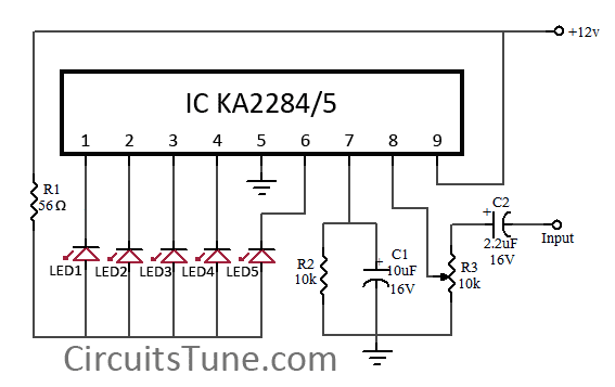
This is a simple circuit diagram of a 5-LED audio VU meter utilizing the ICs KA2284 or KA2285. The KA2284 and KA2285 are monolithic integrated circuits designed as logarithmic display driver ICs. They serve as bar-type display drivers for...
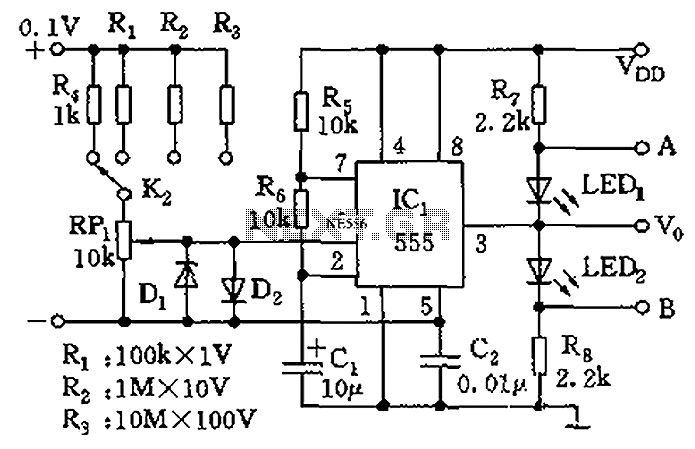
Function: Used to measure the voltage change minute by management before the temperature diodes. Component: IC, Diode, Resistor, 3-1/2 digit LCD (SP521PR). The circuit described functions as a voltage measurement system designed to monitor minute voltage changes, particularly in relation...
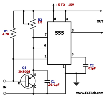
The control terminal at 5 feet and the threshold end at 6 feet represent two internal input voltage comparators. As long as the voltage at 6 feet exceeds the voltage at 5 feet by 5 mV, the 555 timer...
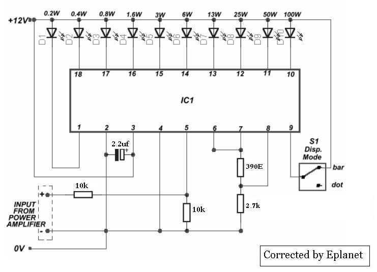
This nifty sound level meter is a perfect one chip replacement for the standard analog meters. It is completely solid state and will never wear out. The whole circuit is based on the LM3915 audio level IC and uses...