
Simple Staircase Generator
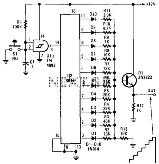
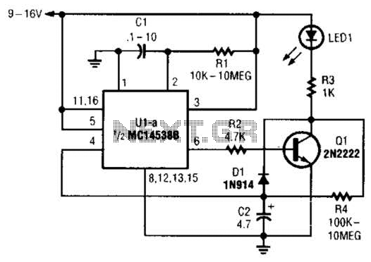
The circuit described involves two primary components: U1, which functions as a switch debouncer, and U2, a decade counter/divider. The switch debouncer (U1) is essential for eliminating noise from mechanical switches, ensuring that when a switch is pressed, only a single transition is registered, rather than multiple erroneous transitions that could occur due to contact bounce.
In the self-generating configuration of this circuit, a resistor is connected between pins 2 and 3 of U1. The value of this resistor should typically be in the range of 10 KOhm, but it can be adjusted to higher values depending on the desired frequency output of the system. This resistor, in conjunction with the capacitor C1, forms an RC timing circuit that determines the frequency of oscillation. By varying the capacitance of C1, the frequency can be fine-tuned to meet specific application requirements.
Additionally, S1, which may serve as an external switch input in non-self-generating configurations, can be omitted in the self-generating version. This allows the circuit to operate independently without external input, making it suitable for applications where a continuous output signal is required. The output from U2, as a decade counter, can provide a sequence of digital signals that can be used for various applications, such as driving LEDs, frequency division, or other digital logic circuits.
Overall, this circuit configuration is useful for creating reliable timing and counting applications in digital electronics, with flexibility in frequency adjustment through passive component selection. U2 is a decade counter /divider, Ul is used as a switch debouncer. For a self-generating system, connect a resisor
between pins 2 and 3 of a Ul value that should be between 10 KOhm and several , depending on desired frequency, Cl can also be varied to change frequency. Also, SI can be omitted in the self-generating version.
🔗 External referenceRelated Circuits
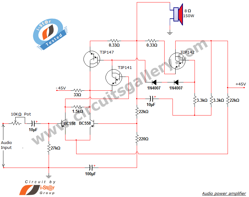
This document presents a new audio power amplifier schematic utilizing TIP darlington pair transistors. It is suitable for both home audio and car audio amplifiers. The TIP142 and TIP147 darlington pair transistors create a push-pull high-power amplifier configuration, while...
The preamp featured has optional tone and balance controls which may be omitted if desired. The input switching may be extended if needed to accommodate more signal sources. In this version, no RIAA (phono) input is provided. See the...
A humidity sensor can be utilized to provide an alert for boat leakage or to notify when books are at risk of being damaged due to heavy rain affecting a compromised roof. Humidity sensors are essential devices that measure the...
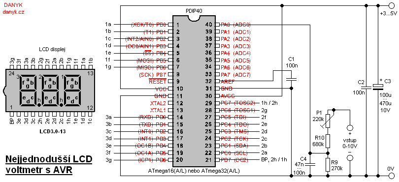
This is likely the simplest digital voltmeter utilizing an Atmel AVR microcontroller and an LCD display. The circuit is managed by a microprocessor IO1 - AVR Atmel ATmega16A, ATmega16L, ATmega16, ATmega32A, or ATmega32. A program is available for free...
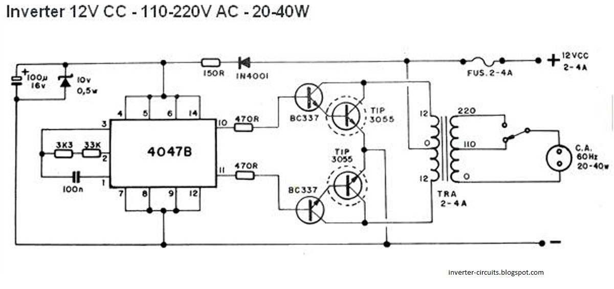
This schematic represents a simple 40W inverter that converts 12V to 220V. It has been functional for four years. The core component of the circuit is a CD4047 integrated circuit (IC) configured as an astable multivibrator. The resistance and...
When power is first applied to the circuit, capacitor C2 begins to charge through LED1, resistor R3, and resistor R4. When the voltage across C2 reaches the input trigger level of operational amplifier U1, the output at pin 6...