
Sensitive Swr Meter
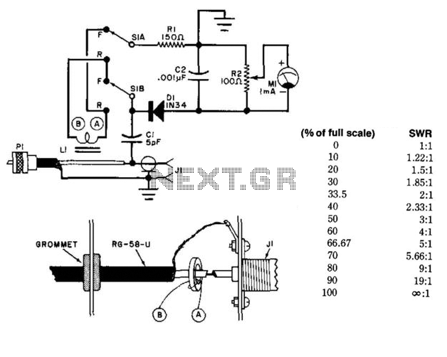
The circuit is designed to provide an efficient means of measuring the SWR, which is crucial for optimizing antenna performance. The toroidal pickup coil is strategically placed around the center conductor of the coaxial cable, allowing it to effectively couple with the electromagnetic fields generated by the RF signals traveling through the cable.
The choice of a Fair-Rite 5963000301 toroidal core is significant due to its high permeability and low core loss, which enhances the sensitivity and accuracy of the measurements. The use of #26 enameled wire for the winding ensures that the coil has a suitable inductance value while maintaining a compact form factor.
In operation, the circuit senses the voltage standing wave ratio by detecting the forward and reflected power in the coaxial cable. The output from the toroidal coil can be fed into a suitable measurement device, such as a microcontroller or an analog meter, to display the SWR value. This information is vital for tuning the antenna system, as a high SWR indicates poor matching between the antenna and the transmission line, which can lead to signal loss and potential damage to the transmitter.
Overall, this circuit configuration is a practical solution for antenna tuning and performance assessment, leveraging the advantages of a toroidal inductor and the inherent properties of coaxial transmission lines. Using a toroidal pickup coil around the center conductor of a coaxial cable, this circuit can be used to measure the SW R of an antenna. LI is two turns #26 enamelled wire on a Fair-Rite 5963000301 toroidal core. 🔗 External reference
Related Circuits
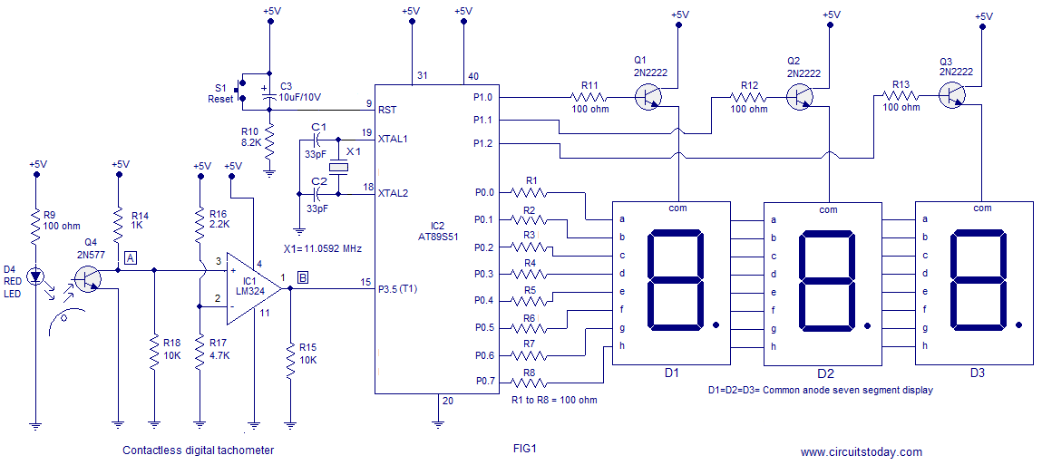
A three-digit contactless digital tachometer utilizing an 8051 microcontroller is presented for measuring the revolutions per second of rotating objects such as wheels, discs, or shafts. The tachometer can measure up to a maximum of 255 revolutions per second...
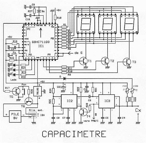
The proposed capacitance is a very powerful assembly to measure in 7 ranges capacitors of 1 pF to 999 uF, with an excellent precision of about 10^-3. The range change is fully automatic. The display shows 3 digits with...
For convenient reading, the display of this tachometer circuit shows the reading in hertz directly. The conversion time will be equal to the gating time. The tachometer circuit is designed to provide a direct digital readout of rotational speed in...

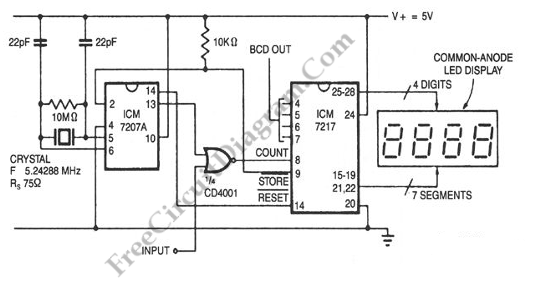
Two versions are provided. The first version is based on the original schematics, with the modification of replacing SMD capacitors with standard through-hole capacitors. The second version features some modifications, including the removal of the transformer and the addition...
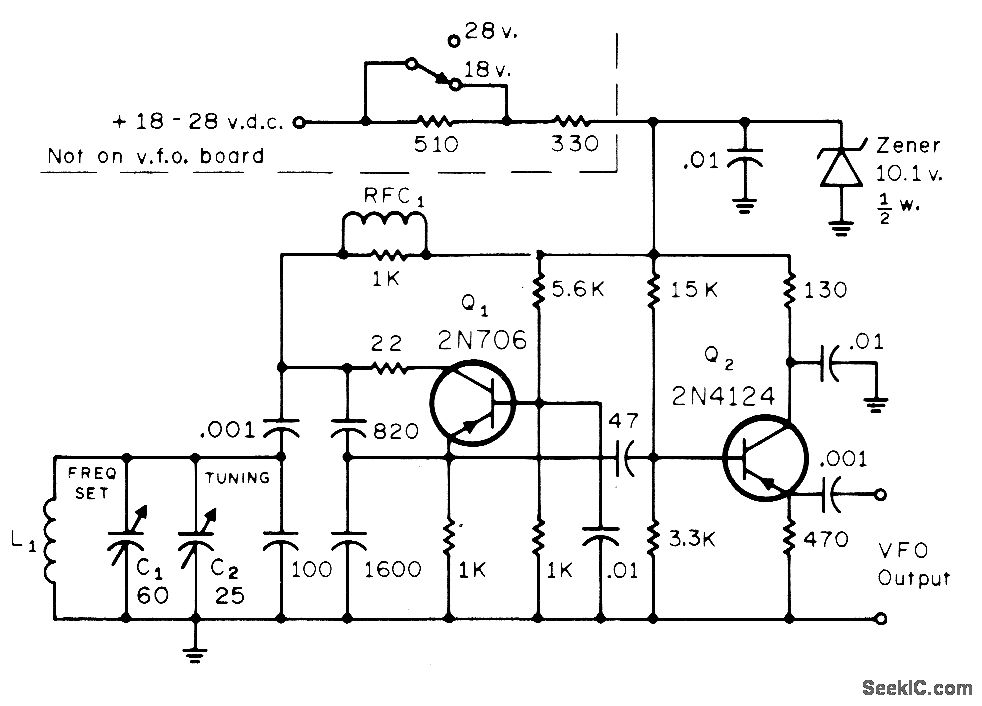
The circuit consists of a standard Colpitts oscillator (Q1) paired with an emitter-follower (Q2), providing reliable performance and sufficient isolation from subsequent stages. Zener regulation ensures stability, even in conditions of low battery voltage, producing an output of approximately...
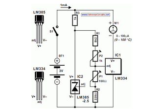
The circuit of the Celsius thermometer in the diagram is based on the well-known Type LM334 from National Semiconductor. This integrated circuit (IC) serves as a sensor that provides temperature readings. The Celsius thermometer circuit utilizes the LM334 integrated circuit,...
Warning: include(partials/cookie-banner.php): Failed to open stream: Permission denied in /var/www/html/nextgr/view-circuit.php on line 713
Warning: include(): Failed opening 'partials/cookie-banner.php' for inclusion (include_path='.:/usr/share/php') in /var/www/html/nextgr/view-circuit.php on line 713