
SOUND LEVEL METER
The described circuit functions as a sound level meter, utilizing a combination of analog components to capture, process, and display audio signal levels. The power supply, a 9-V battery, is sufficient for extended operation, and the low current draw ensures longevity. The microphone (MIC1) acts as the primary sensor, converting sound waves into electrical signals, which are then buffered to maintain signal integrity. The NE614 (U1) serves as the core processing unit, with its input impedance designed to optimize performance and linearity of the received audio signals.
The RSSI (Received Signal Strength Indicator) output is crucial for determining the sound level, as it translates the SPL into a corresponding voltage. The filtering capacitor (C10) is essential for removing unwanted high-frequency noise, ensuring that the output is representative of the actual sound level. The operational amplifier (U2-b) enhances the signal from the RSSI, allowing for a more accurate representation of sound levels on the display.
The display system, utilizing the LM3914 (U5), provides a clear visual indication of sound levels, allowing users to easily interpret the information. The internal voltage regulation ensures stable operation, and the design allows for calibration through the use of the LM334 (U4) and potentiometer R17, accommodating variations in microphone sensitivity.
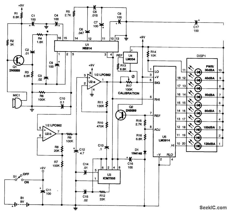
The ICM7555 timer (U3) adds a timing element to the circuit, enabling the display to refresh at a consistent rate, thus providing a stable readout. This combination of components and design choices results in a robust and effective sound level meter capable of measuring and displaying sound levels accurately within the specified range.Power for the circuit is provided by B1, a 9-V battery. Total battery current is 14. 5 mA, so an alkaline battery should last about 250 hours. Audio signals are picked up by microphone MIC1. The output of MIC1 is buffered by Q1 to maintain the 3000- © load of resistor R2. The input impedance at pin 16 of the NE614 (U1) is 1600 © to reduce the gain on the high end and preserve the RSSI linearity. The RSSI signal is a current source that flows through R6 to establish a voltage at pin 5 of U1;the RSSI output voltage is a function of the input SPL. Capacitor C10 removes high-frequency components. The slope of the RSSI line is nominally 0. 084VCC/10 dB. Op amp U2-b is configured as a non-inverting voltage buffer with a gain of 1. 2; multiplied by the RSSI slope, this produces a slope of 0. 1VCC/10 dB. The display, DISP1, is a 10-bar LED that is used to indicate sound level in 10-dB increments from 30 to 120 dB(A).
The display is driven by an LM3914linear bar-graph driver, U5. The internal voltage regulator of U5 functions by establishing a constant current through R15 because the voltage between pins 7 and 8 is maintained at 1. 25V. The resulting voltage at the emitter of Q2 is about 5V, which powers U1, U3, and the internal voltage-divider string of U5 at pin 6.
Each segment of the display will increase by 10 dB, independent of the exact magnitude of VCC While the slopes of the display driver and the RSSI signal are the same, they might not have the sanit offset. For that reason, an LM334, U4, is used to source a constant 10- A current through R17 to generate a fixed off-set voltage on top of the composite RSSI voltage at the output of U2-a.
By adjusting the value of potentiometer R17, differences in microphone sensitivity can be accommodated so that the display reads properly from 30 to 120 dB(A). The proper readout of the display is also ensured by an ICM7555 timer, U3, which is configured as a self-excited square-wave oscillator; the resulting peak-Lo-peak, 1-kHz signal of the timer is almost one step size of DISP1.
🔗 External reference
Related Circuits
CW is the simplest form of modulation. The output of the transmitter is switched on and off, typically to form the characters of the Morse code. CW transmitters are simple and inexpensive, and the transmitted CW signal doesn’t occupy...
The PIC Microchip Processor must be programmed before it will function as a Volt & Amp meter. There are many internet sites and PIC programmers that you can use. I used a Microchip MPLAB ICD 2 during the project....
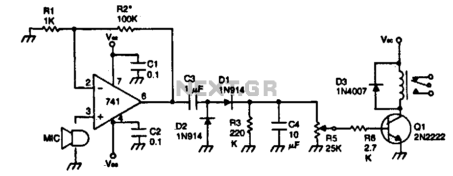
The device remains dormant (in an off condition) until a sound activates it. The input stage consists of a 741 operational amplifier configured as a non-inverting audio amplifier with a gain of approximately 100. To increase the gain, the...
The LED power Meter is a simple RF detector using diodes to charge a capacitor. The voltage developed across the capacitor is indicated by a multimeter set to a low voltage range. The circuit is soldered together without the...
This device estimates the amount of water remaining in the water tank of a caravan or camping unit. The water level estimation device utilizes a combination of sensors and microcontroller technology to provide accurate readings of the water level in...
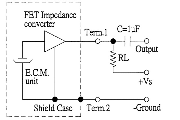
The back of the electret microphone resembles the drawings of the CUI Inc part number CMA-4544PF-W, which will be included in the parts kit. While debugging the data logger software on Windows, an oscilloscope practice lab was conducted using...