
Wireless Microphone
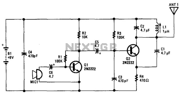
In this circuit, Q1 serves as a critical amplification stage, enhancing the audio signal captured by the electret microphone (MIC1). The electret microphone converts sound waves into an electrical signal, which is typically weak and requires amplification to be effectively processed. The amplified output from Q1 is then directed to oscillator Q2. The role of Q2 is to modulate the audio signal onto a carrier wave, a technique commonly used in radio frequency (RF) applications to enable the transmission of audio over longer distances.
The tank circuit, composed of L1 (a variable inductor) and C1 (a capacitor), is tuned to resonate at a frequency of 88 MHz. This frequency is significant as it falls within the FM radio band, allowing for efficient transmission of the modulated audio signal. The variable inductor L1 enables fine-tuning of the resonant frequency, which is essential for matching the circuit to the desired transmission frequency and optimizing performance.
The antenna, which is a simple length of wire measuring between 6 to 8 inches, is designed to radiate the modulated signal effectively. The length of the antenna is critical, as it should be approximately a quarter wavelength of the operating frequency for optimal radiation efficiency. Given that 88 MHz corresponds to a wavelength of approximately 3.4 meters, the chosen antenna length is suitable for effective transmission in this frequency range.
Overall, this circuit configuration is typical for low-power FM transmitters, where the combination of amplification, modulation, and proper antenna design facilitates the transmission of audio signals over short distances. The careful selection of components and their arrangement in the circuit is crucial for achieving the desired performance characteristics. Ql amplifies the output from an electret microphone MIC1. Audio is fed into oscillator Q2, which modulates the signal. LI CI is a tank circuit for operation in the 88-MHz region. The antenna is a 6- to 8-inch piece of wire. LI is a variable inductor in the l- range. 🔗 External reference
Related Circuits
The FM Wireless Microphone has gained popularity among both beginners and experienced constructors. It has been utilized in guitars and as a component of remote control systems. There have been numerous requests for a higher-powered circuit with improved microphone...
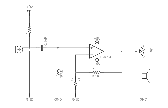
Afroman discusses the fundamentals of utilizing an operational amplifier to amplify small voltage signals and constructs a circuit designed to detect very faint sounds using a microphone. For further details about amplifiers, it is recommended to search for inverting...
An RF condenser design powered by 12V was supplied to the microphone through the microphone cable using a phantom circuit. This marks the first known application of a phantom circuit for microphone powering. Around 1970, Neumann introduced the Fet-80...
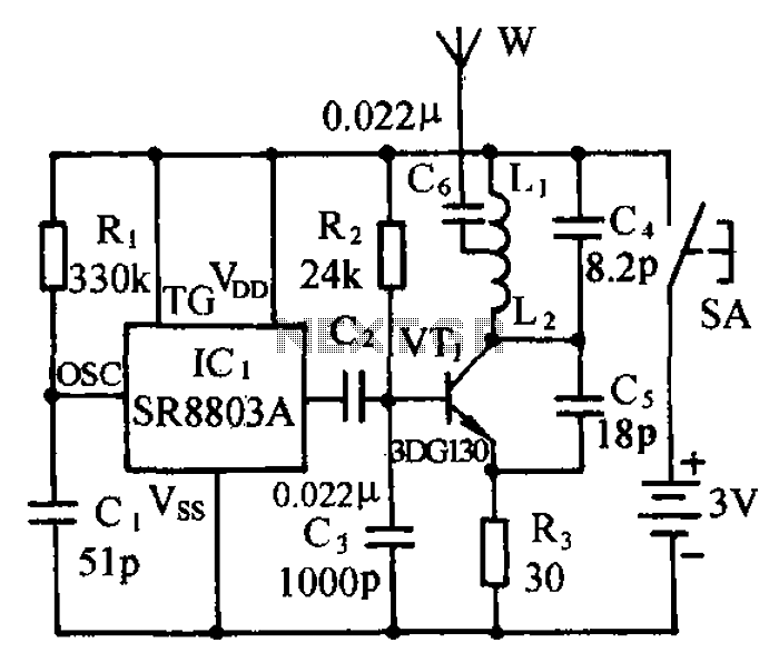
The circuit consists of a language and sound FM transmitter. It is mounted on a 25mm x 35mm PCB, designed to be placed on a table. When activated by pressing the micro switch SA, the circuit transmits an FM...

This design circuit is for a stereo amplifier intended for a high-sensitivity stereo parabolic microphone, enabling the listening of distant sounds. Unlike typical parabolic microphones that are monophonic, this unit features a stereo audio path, resulting in more realistic...
A microphone amplifier designed for use with either Electret Condenser Microphone (ECM) inserts or dynamic inserts, constructed with discrete components. The preamplifier circuit is self-stabilizing and sets its quiescent point at approximately half the supply voltage at the emitter...