
fm stereo decoder
A typical Foster Seeley FM discriminator, commonly found in older transistor portables and valve hi-fi tuners, is illustrated. The output filter capacitor (C3) and resistor (R3) serve as de-emphasis components required for mono reception, with specific values set for a time rate of 50 microseconds for UK FM broadcasting. If these components are left in place when connecting the stereo decoder, the results will be unsatisfactory due to distortion of the 19 kHz pilot tone and stereo signal components, resulting in poor separation. An alternative circuit without the de-emphasis components is also described, which is suitable for stereo conversion.
A phase correction circuit is introduced for tuners with low IF response, specifically for the pulse counting receiver. The Double Conversion Pulse Counting FM Superhet Receiver, featuring a 10.7 MHz first IF stage, derives its de-emphasis from the output RF bypass capacitor (C28) on the discriminator. Removing this component or reducing its value can lead to instability or malfunction. RV1 in the phase correction circuit acts as an audio attenuator, widening the bandwidth necessary for proper stereo reception, specifically for the pulse counting tuner. RV2 and C1 form a parallel capacitor network in series with the input, delaying the stereo signal components relative to the 19 kHz pilot tone, achieving a separation of approximately 30 dB.
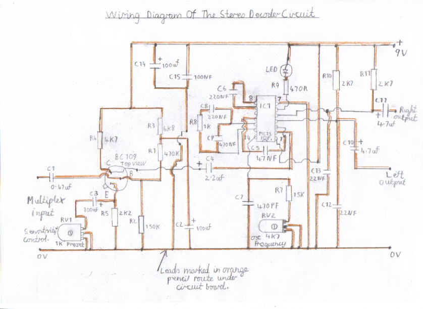
The suggested stereo decoder circuit is briefly explained. The TR1 BC109 transistor functions as an input preamplifier for tuners with low output sensitivity, crucial for the pulse counting receiver to counter the output attenuation from earlier stages. RV1 serves as the preamp gain control, requiring adjustment through trial and error to avoid overloading the preamp, which could hinder clear and undistorted stereo reception. RV2 is the voltage-controlled oscillator (VCO) tuning potentiometer, adjusted counterclockwise until the stereo indicator lamp activates. This lamp can be a low current LED, ideally rated for 20 to 40 milliamps, with a maximum draw of 100 milliamps from the LED output on this IC. An improved version of this circuit is anticipated in late August, which will include filtering of the 19 kHz pilot tone and an output buffer stage to enhance stability when interfacing with various audio amplifiers, addressing previous issues with the current design.
The schematic for this stereo decoder circuit should include the following components:
- **MC1310P IC**: The core stereo decoder integrated circuit.
- **TR1 (BC109)**: Input preamplifier transistor.
- **C1**: Parallel capacitor for delaying stereo signal components.
- **RV1**: Preamp gain control potentiometer.
- **RV2**: VCO tuning potentiometer.
- **C3 and R3**: De-emphasis components (to be omitted for stereo conversion).
- **C28**: RF bypass capacitor for the discriminator.
- **LED**: Indicator for stereo reception.
The circuit should be designed with careful consideration of component values and configurations to ensure optimal performance, particularly in terms of signal integrity and separation quality when converting from mono to stereo.This part of my site features a stereo decoder circuit suitable for both my pulse counting FM Receivers and other types of FM Tuner, such as the old valve type that incorporates a Foster Seeley or Ratio Detector. This particular stereo decoder IC, MC1310P was popular during the mid 1970s in music centres and for hi fi enthusiasts that wanted to co
nvert there old mono tuners to stereo. Before this MC1310P IC was around, building a stereo decoder was a difficult task and was actually harder to set up and align then the FM Receiver itself, obvious because you had the 19KHZ and 38KHZ pot core coils to wind which required 1000s of turns of enamelled copper wire in the bargain. You also needed at least 5 valves or 10 transistors to get a decoder that really performed well. Many people have been led to believe that you just hook up the line output from an existing mono FM receiver to the decoder and hope for the best.
This is one of the worst pitfalls to get into and I am going to do a brief explanation of how to avoid this. Picture 3 is a typical Foster Seeley FM discriminator found in old transistor portables and valve Hi FI tuners.
The output filter capacitor C3 and the R3 are the De-Emphasis components required to receive mono reception. These components vary in value and in this particular discriminator it is set at a time rate of 50 microseconds for UK FM broadcasting.
If you simply leave these components in and connect the stereo decoder, you will get very disappointing results because these components will severely distort the 19KHZ pilot tone and stereo signal components leading to poor separation. Picture 4 is the same Foster Seeley discriminator except the De-Emphasis components, R3 and C3 are not included.
This later circuit should now be ok for a stereo conversion. Please always bear this in mind before attempting a stereo conversion on a old mono tuner. Picture 1 is a phase correction circuit designed for tuners that have a low IF response. In the case of the pulse counting receiver, this is needed for the simple reason. The Double Conversion Pulse Counting FM Superhet Receiver With 10. 7 MHZ First IF Stage gets its De-Emphasis from the output RF bypass capacitor C28 on the discriminator. Removing this component or reducing its value will cause the receiver to become unstable or not work at all.
RV1 on the phase correction circuit, is a simple audio attenuator to overcome this problem, as it widens the bandwidth to make stereo reception work properly and is only needed for the pulse counting tuner. RV2 and C1 is a parallel capacitor network connected in series with the input and the purpose of these components is to delay the stereo signal components relative to the 19KHZ pilot tone giving a separation of about 30db.
Picture 2 is the suggested stereo decoder circuit which I will explain briefly. The TR1 BC109 transistor forms a input preamp designed for tuners that have a low output sensitivity and in the case of the pulse counting receiver, this is needed to overcome the attenuation of the output in the earlier stage to make stereo work properly. RV1 is the preamp gain control and is adjusted with trail and error, if signals are found to be overloading the preamp, preventing clear undistorted stereo reception.
RV2 is the VCO voltage controlled oscillator tuning potentiometer and is adjusted in the anticlockwise direction until the stereo lamp lights. The stereo lamp can be any low current LED preferably 20 to 40 milliamps. It must be born in mind that you must not draw more then 100 milliamps from the LED output on this particular IC.
NBThere is to be an improved version of this circuit around late August which will involve filtering of the 19KHZ Pilot Tone and an output buffer stage which should hopefully improve the stability of this circuit when driving various types of audio amplifier which has been an issue with this present circuit. 1. Please refer t 🔗 External reference
Related Circuits
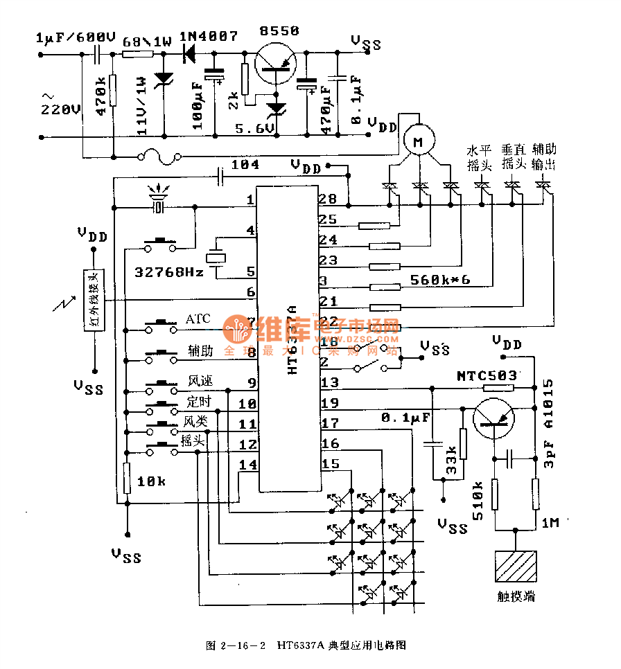
The HT6337 is an infrared remote control receiving decoder circuit specifically designed for electric fan applications. It is housed in a 28-pin dual-row DIP package, with the compatible model being HT12C. The HT6337 is part of a series of...
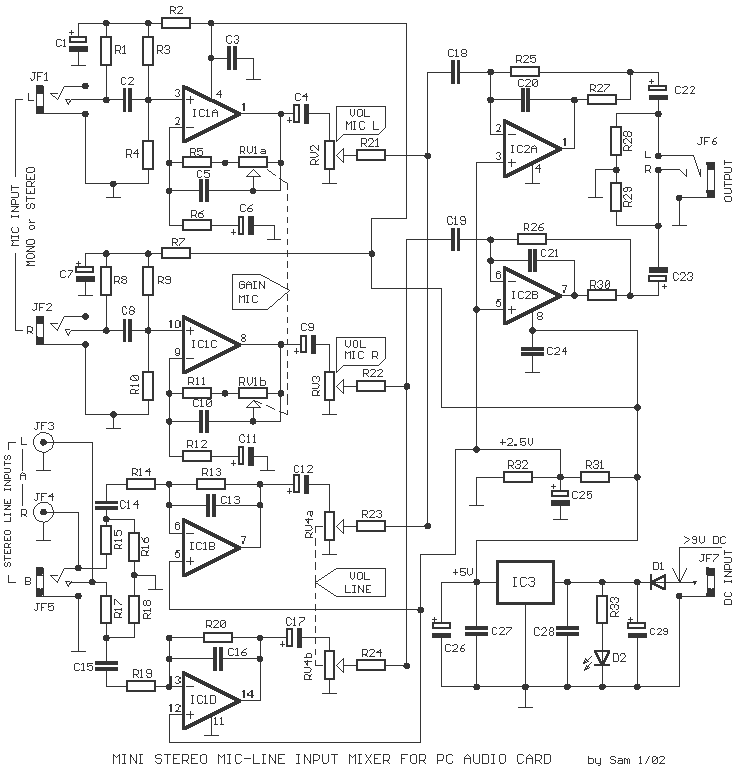
Most cards of sound in computer are deprived stereo input for microphone; on the contrary, they have stereo input for high level (Line). The circuit uses the input Line of the sound card in order to connect two mono...
This device and all information contained on this website is for educational purposes only. This device must be used in conjunction with any and all local, provincial, and federal laws. It is the responsibility of the end user to...
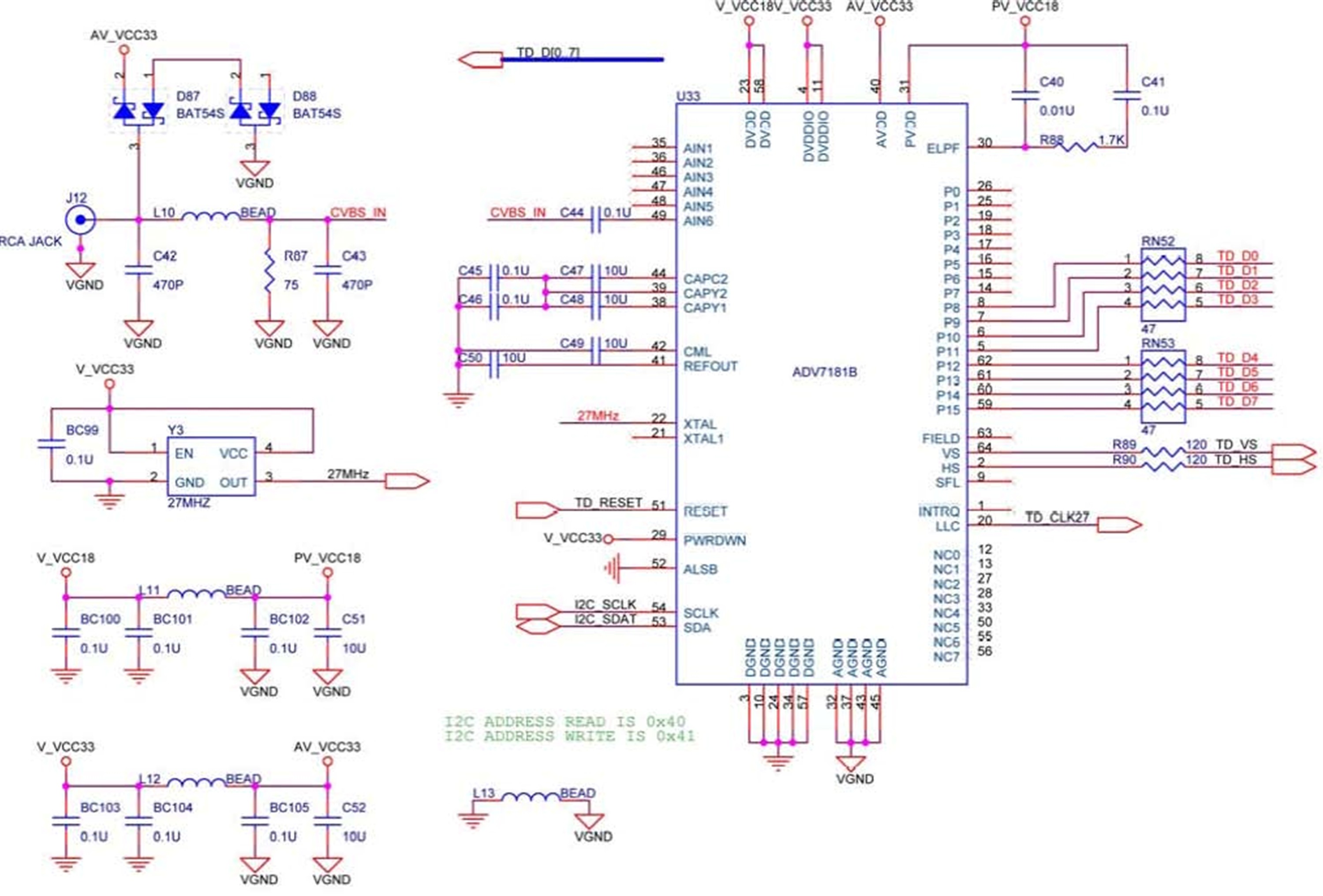
The DE2 board features an Analog Devices ADV7181 TV decoder chip. The ADV7181 is an integrated video decoder that automatically detects and converts standard analog baseband television signals (NTSC, PAL, and SECAM) into 4:2:2 component video data, which is...
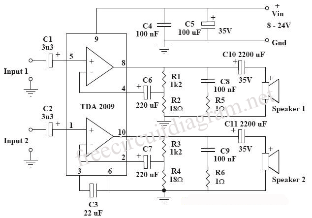
This circuit is a diagram of a mini amplifier. The amplifier circuit has a power output of 10 watts and is well-suited for car audio applications. It utilizes the TDA2009A integrated circuit as the power amplifier. To prevent excessive...
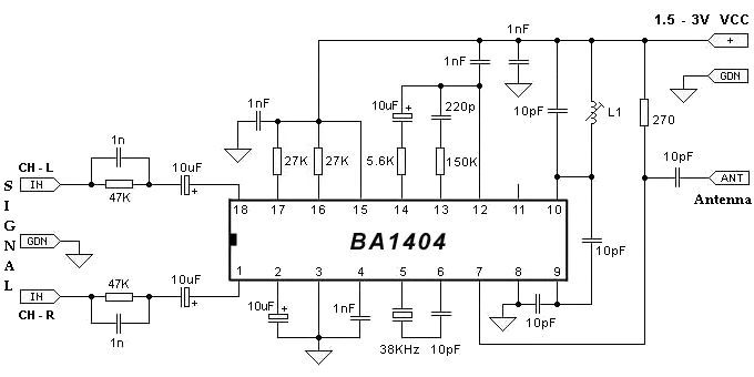
The BA1404 can be utilized to create a simple and effective FM stereo modulator electronic project. This BA1404 FM stereo modulator device operates within the FM broadcast band (75-108 MHz) and requires only a few common external components. The...