
Stereo to Mono Converter
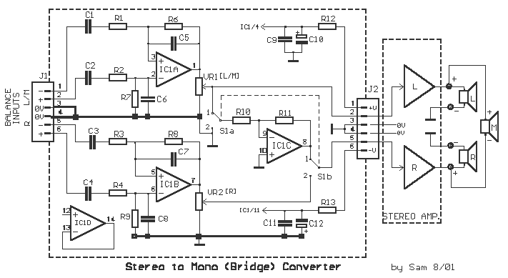
Part List
R1-2= 47Kohms C1-2= 1uF 100V 5% IC1= TL074
R3-4= 47Kohms C3-4= 1uF 100V 5% S1= 2X2 SW.
R5-6= 47Kohms C5-6= 33pF VR1-2= 10Kohms Log. pot.
R7-8= 47Kohms C7-8= 33pF .
R9-10-11= 47Kohms C9-11= 100nF 100v .
R12-13= 22 ohms C10-12= 47uF 25V .
?ll metal film 1/4W 1% J1-2= 6pin Connector
This circuit is designed to facilitate the transformation of a standard stereo amplifier into a high-power mono amplifier by bridging the two channels. The bridging process involves reversing the phase of one channel, effectively doubling the output voltage and, consequently, the power. The use of a TL074 operational amplifier ensures low noise and high performance in the signal processing stages, allowing for precise phase manipulation and signal conditioning.
The inclusion of high-quality components such as metal film resistors and quality capacitors is crucial for maintaining signal integrity and achieving the desired output characteristics. The potentiometers (VR1 and VR2) provide user-adjustable control over the gain of each channel, allowing for fine-tuning of audio levels, which is particularly useful in live sound applications or studio settings.
The circuit also accommodates both balanced and unbalanced inputs, making it versatile for various audio sources. The switch S1 allows for easy configuration between stereo and bridged modes, providing flexibility depending on the application. The stabilized ±15V power supply ensures consistent performance across varying load conditions, which is essential for high-power audio applications.
Overall, this circuit is an effective solution for audio engineers and enthusiasts looking to maximize the output capabilities of their stereo amplifiers while maintaining high fidelity in sound reproduction.This is a very useful circuit for those who want to transform a stereo Power Amplifier, to mono, bridging two channels from him , reversing the phase of the one power amplifier [R] and the polarity, with these connections we can have 4X times the output power (double the output voltage ) . For example : if we use the circuit to a stereo amplifier 2X50W, will have 1X200W output , if power supply assent.
In the connector J1, we can connect two type plugs (XLR) Cannon, and input of two channels it's symmetric (electronic balance). With potesometer VR1 and VR2, we regulate the level of each channel separately (stereo), switch S1a-b [place 2].
When bridging two amplifiers, with the switch S1a-b [place 1], then the level him we regulate only with the VR1. The department of channel [ R ] is suppressed and the input is given only in [ L ] channel. Simultaneously inputs in use the inversion department of phase round the IC1c, driving second power amp. [ R ], with reverse polarity, from [ L ] channel. The output now it should him we take from two [+] positive output final amplifiers. In the circuit it appears association the loudspeakers and for the two cases (stereo - bridge). In order to we have results of precision, should the resistances of input differential amplifiers, be metal film 1%, pontesometer, the capacitors and switch S1, good quality.
The power supply of circuit is ± 15V, stabilised. If you want to use the inputs, no as symmetrical (balance), but as asymmetrical (unbalance), you can connect in 0V, the negative inputs of signal J1/1 [L/mono] and J1/5[R ]. The asymmetrical signal now enters in the positive inputs, J1/2 and J1/6. Part List R1-2= 47Kohms C1-2= 1uF 100V 5% IC1= TL074 R3-4= 47Kohms C3-4= 1uF 100V 5% S1= 2X2 SW. R5-6= 47Kohms C5-6= 33pF VR1-2= 10Kohms Log. pot. R7-8= 47Kohms C7-8= 33pF . R9-10-11=47Kohms C9-11= 100nF 100v . R12-13= 22 ohms C10-12= 47uF 25V . ?ll metal film 1/4W 1% J1-2= 6pin Connector 🔗 External reference
Related Circuits
The LMC568 is an amplitude-linear phase-locked loop that includes a linear voltage-controlled oscillator (VCO), fully balanced phase detectors, and a carrier detect output. It utilizes LMCMOS technology to achieve high performance while maintaining low power consumption. The VCO features...
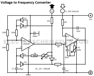
This voltage-to-frequency converter circuit features a voltage-controlled oscillator with a small deviation of 0.5%. The integrated circuit IC1 operates as a multivibrator. The voltage-to-frequency converter circuit is designed to convert an input voltage into a corresponding frequency output. The core...

The following diagram illustrates the circuit of a 20-band stereo graphic equalizer designed to control audio signals within specific frequency ranges. This circuit should be connected prior to the amplifier circuit to ensure optimal performance. The 20-band stereo graphic equalizer...
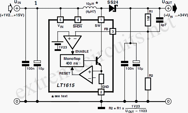
A DC/DC converter IC from Linear Technology, the LT1615 step-up switching voltage regulator, is capable of generating an output voltage of up to +34V from a supply voltage ranging from +1.2V to +15V, utilizing only a few external components....
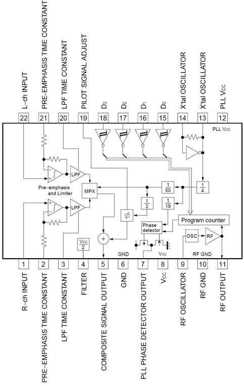
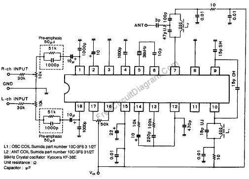
The BH1417 FM Transmitter architecture from RHOM is a compact solution that integrates multiple features into a single package. It includes pre-emphasis and a limiter to ensure that music is transmitted at the desired audio level, as well as...
This audio amplifier design utilizes two LM3886 chips per channel in a parallel configuration, based on the PA100 parallel amplifier detailed in National Semiconductor's application note AN1192. The amplifier can deliver approximately 50W into an 8-ohm speaker and 100W...