
TRIAC dimmer light circuit with dual time constant
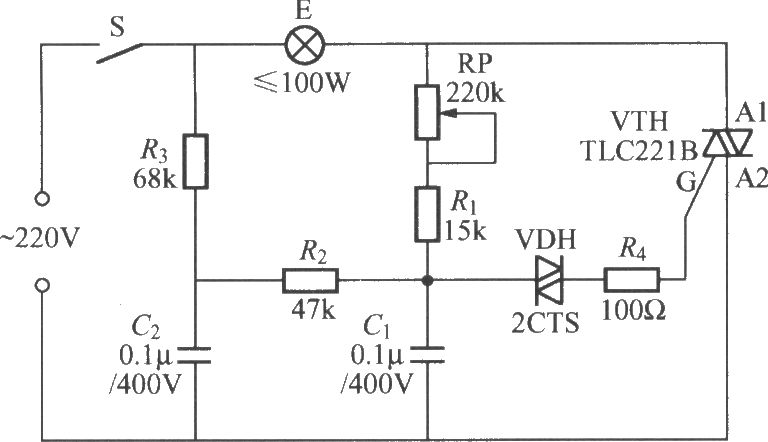
The Triac dimming light circuit utilizes a Triac as the main switching element, allowing for the control of the power delivered to a load, typically an incandescent bulb. The dual time constant behavior is achieved through the strategic selection of resistor and capacitor values, specifically R3 and C2. This arrangement allows for a rapid response to changes in the control signal, thereby reducing the lag time associated with the dimming process.
In this configuration, capacitor C1 charges and discharges through the resistors R2 and R3, alongside capacitor C2. The charge time of C2 is crucial as it influences the timing of the Triac's triggering point. By increasing the value of R3 and C2, the circuit can effectively manage the charge and discharge cycles, allowing for smoother transitions in light intensity. This is particularly beneficial in applications where precise control over lighting conditions is necessary, such as in theater lighting or mood lighting environments.
The circuit can be further optimized by selecting components that minimize thermal drift and ensure stable operation across varying temperatures. Additionally, incorporating snubber circuits may protect the Triac from voltage spikes, enhancing the reliability of the dimming function. Overall, this Triac dimming light circuit design presents an effective solution for mitigating lag and improving light transition performance in dimmable lighting applications.In order to solve the lag and light transition phenomena, it can use the Triac dimming light circuit shown in the figure with dual time constant. The circuit increases R3, C2 resistor-capacitor network, and the reducing charge on capacitor C1 can get promptly complement through C2, R2, R3 circuit, it can effectively reduce the lag and lighting transitions a..
🔗 External reference
Related Circuits
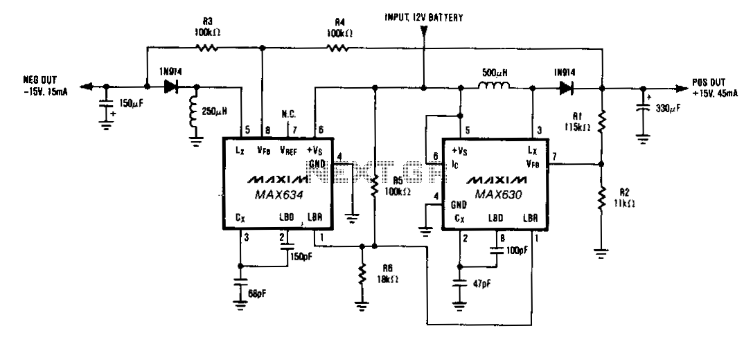
A MAX634 inverting regulator is combined with a MAX630 to provide a dual tracking ±15 V output from a 12-V battery. The reference for the -15 V output is derived from the positive output via resistors R3 and R4....
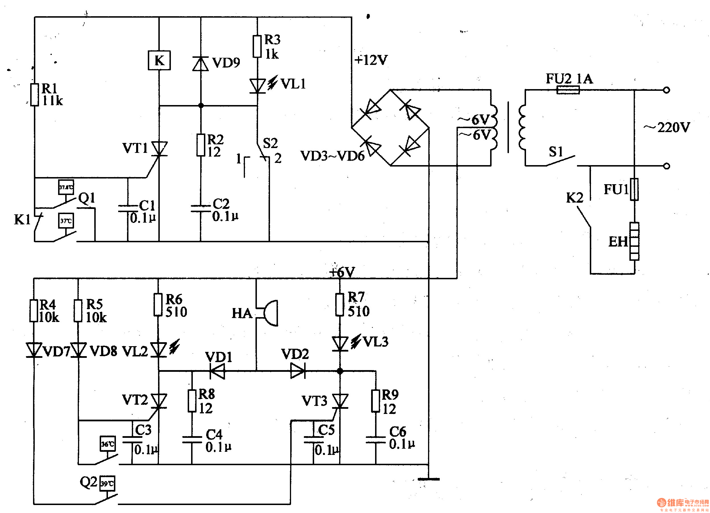
The egg hatching incubator circuit comprises a power supply circuit, a constant temperature control circuit, and a sound and light alarm circuit, as illustrated in Figure 4-7. The power supply circuit includes a power switch (S1), a fuse (FU2),...
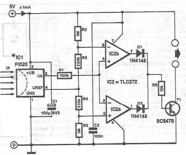
This infrared detector circuit is designed using the PID20 integrated circuit manufactured by Siemens, which converts thermal radiation into electrical impulses. It includes an operational amplifier and several electronic components. The output signal at pin 3 is compared with...
Amplifier with IC number TDA7293 for processing sound systems. This amplifier includes inputs for a radio, TV, stereo, or other line-level devices. It also features a phono input for a record player, guitar, microphone, or other unamplified sources. With...
This schematic has been modified from an old Bell & Howell projector amplifier for model 302, utilizing PP 6V6 tubes with a 12AU7 phase inverter (PI). The PI circuit appears to be closest to a "floating paraphase." There is...
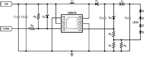
The LM3410 constant current LED driver is a monolithic integrated circuit that enables the design of high-efficiency, low-cost lighting solutions using a minimal number of electronic components. It employs current-mode control and internal compensation to ensure optimal performance across...