
Stereo balancer
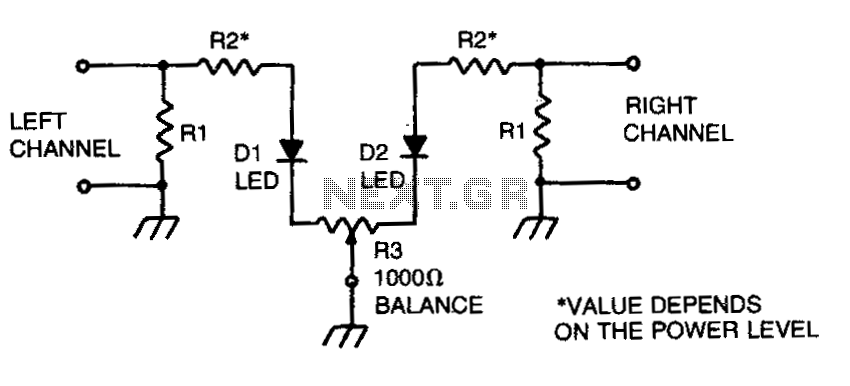
This circuit functions as a stereo balancer, allowing for precise gain matching between two audio channels. It employs a feedback mechanism using resistors R2 to sample the output signal across the load resistors of each channel. The choice of resistor values is crucial; for example, using 2 kΩ resistors for 20 mA LEDs ensures that the circuit operates within safe limits while providing adequate brightness. The adjustment of R3 serves as a fine-tuning mechanism, allowing the user to match the brightness of the two LEDs, which visually indicates the balance between the channels.
In practical applications, the circuit can be integrated into various audio systems, enhancing the listening experience by ensuring that both channels deliver sound at the same level. The setup process is straightforward, requiring only the connection of inputs to the power amplifier and subsequent adjustments to achieve the desired output. When utilized with loudspeakers, the circuit's flexibility allows for easy adaptation by removing the load resistors and directly connecting the speakers, maintaining functionality without compromising audio quality.
Overall, this stereo balancer circuit is an effective solution for achieving equal gain levels in audio applications, making it suitable for both amateur and professional audio setups.This circuit will allow you to set the gain of two stereo channels to the same level. The signal across the two channel-load resistors is sampled by resistors R2. (Values of these resistors will depend upon the power level) For most 20 milliampere LED, use approximately 2 K per watt. (For a 10-watt system use a 25,000 ohm resistor) To set up, short the two inputs and connect them to one channel of a power amplifier.
Apply a signal and adjust R3 until both LEDs glow at the same brightness level The balancer is ready for use. Connect the inputs of the stereo balancer across the output of the power amplifier, and then turn up either the independent volume controls, or the balance control until both LEDs glow at the same level. To use this circuit in-line with loudspeakers, disconnect both Rls, and use the speakers as the load.
🔗 External reference
Related Circuits
If a stereo amplifier lacks an input for a record player, it is advisable to utilize this circuit between the turntable and the amplifier. The output from the turntable adheres to a gain-bandwidth curve known as the RIAA compensation...
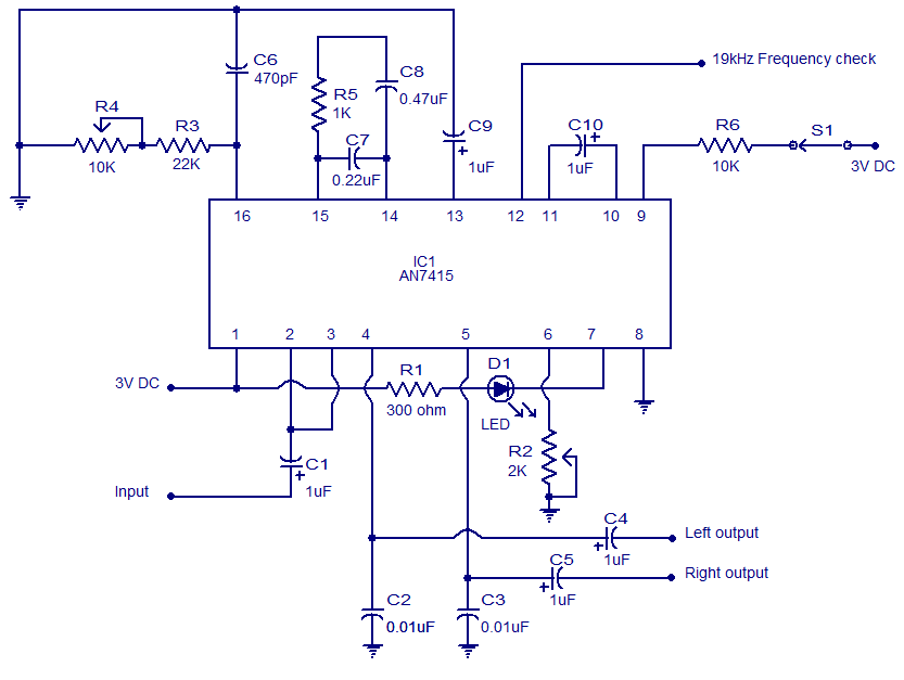
This weblog focuses on electronic circuit schematics, PCB design, DIY kits, and electronic project diagrams. The circuit presented is a stereo FM PLL demodulator based on the AN7415. C1 serves as the input coupling capacitor, blocking any DC voltage...
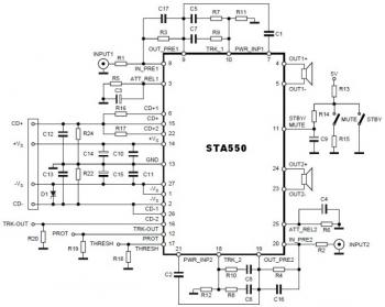
This is a stereo amplifier circuit diagram. The amplifier will produce stereo output channels with a power audio output that can reach up to 70W for each channel. The amplifier is built using the STA550 chip from STMicroelectronics. It...
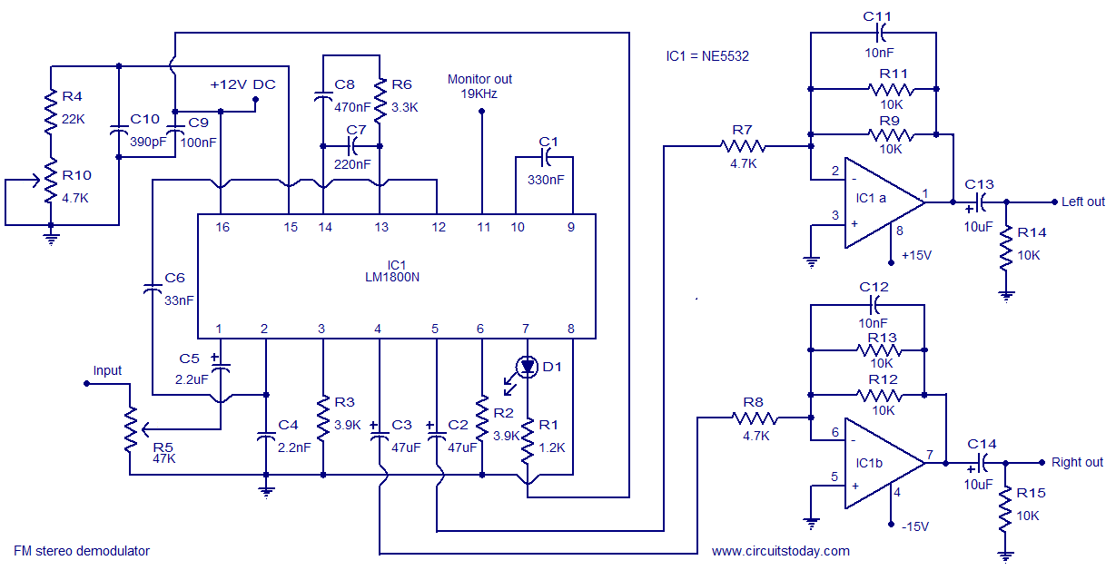
The following circuit illustrates the LM1800 IC Integrated FM Stereo Demodulator Circuit. Features include excellent sound quality and high-quality FM stereo. The LM1800 Integrated Circuit (IC) serves as a highly effective FM stereo demodulator, designed to deliver superior audio performance...
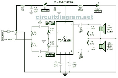
This is the circuit diagram of a USB-powered computer speaker, commonly referred to as multimedia speakers for PCs. The circuit features a single-chip design, operates on a low-voltage electrical power supply, is compatible with USB power from computers, includes...
A general purpose audio power amplifier is a must have for the electronics amateur. It's not a good thing to use your HiFi set for an experiment, when there's a risk of blowing its transistor out. Amplifier for your...