
STHS Computer Technology
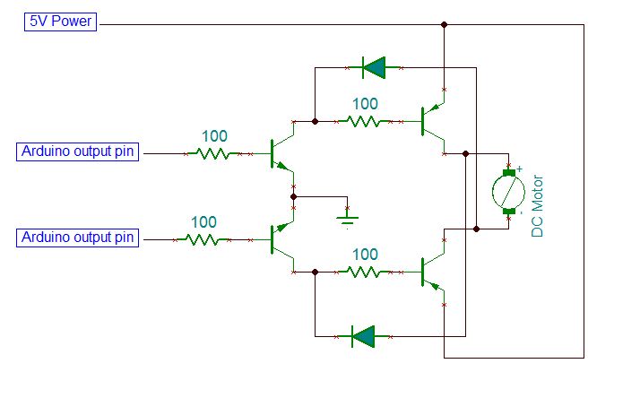
To create an effective H-bridge circuit for controlling DC motors, it is essential to understand the basic configuration and operation of the components involved. An H-bridge consists of four switches (transistors or MOSFETs) arranged in an "H" shape, allowing current to flow in either direction through the motor, thus enabling forward and reverse rotation.
In this setup, the Arduino will control the H-bridge by sending signals to the gates of the transistors. When one pair of transistors is activated, the motor will rotate in one direction, while activating the other pair will reverse the motor's direction. The control signals can be generated using digital output pins from the Arduino, with one pin dedicated to each direction of the motor.
For the QRD line sensors, the circuit typically includes an infrared LED and a phototransistor. The LED emits infrared light, which reflects off the surface below it. The phototransistor detects the reflected light. When the sensor is over a dark line, less light is reflected, resulting in a lower signal at the phototransistor's output. Conversely, when the sensor is over a lighter surface, more light is reflected, yielding a higher output signal.
To ensure reliable operation, the Arduino must read the sensor values and establish a threshold. By determining the highest and lowest values from the sensors, the midpoint can be calculated and used as the threshold value. This threshold will allow the robot to make decisions based on the sensor readings, enabling it to follow the line accurately.
Testing of both the H-bridge circuits and the QRD line sensors is crucial. For the motors, the Arduino sketch should be modified to test each motor's functionality in both directions, ensuring proper operation. For the QRD sensors, the Arduino should continuously read values and compare them against the established threshold to maintain accurate line following behavior. Proper calibration and testing will ensure the robot performs as intended, effectively navigating its environment.On the breadboard, build two bi-directional motor control circuits (also known as "H-bridge") circuits. These circuits will control the two DC motors that drive the wheels. Each circuit will have two wires from the Arduino (one for forward, one for backward) to control the circuit, and two wires from the single DC motor that it is controlling.
You should test your circuits to ensure you can control both motors in both forward and reverse directions. Here is a sample Arduino sketch you can use to test the motors. Edit the code to check each motor and direction, and double-check the circuit for any motor that doesn`t behave as expected.
Here`s the schematic circuit diagram of one QRD line sensor connected to the Arduino. You will be wiring two of these, so your robot can tell whether it is on the line, off a little bit to the left, off a little bit to the right, or completely off the line. Now test that both QRD1114`s are operating correctly, and sending a proper signal to the Arduino. Here is a sample Arduino sketch to test the circuits. Make sure you are getting a good range of values from both sensors between light and dark. Make a not of the highest and lowest values you get from each sensor. You will use a value half way in between these for your "cut off" or "threshold" value. This is the boundary value we`ll use to decide if the sensor is seeing the dark line or not. 🔗 External reference
Related Circuits
This circuit is beneficial for connecting a computer to homemade robotics. It is straightforward to construct and operate, capable of controlling two DC motors of varying current and voltage ratings, contingent on the specifications of the relays used. Additionally,...
A mouse operates on two axes: "X" and "Y". When the mouse is moved horizontally, the "X" wheel inside the mouse rotates, and when moved vertically, the "Y" wheel rotates. The movement of the mouse results in the wheels...
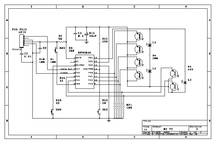
Flight Computer V1.0: B1 PC Board U1 80C32 microprocessor U2 27C256-12 32Kx8 ROM - 120nS U3 74HC373 U4 LM340T-5 5V regulator (may be a 7805 part) U5 43C256-15 32Kx8 RAM - 150nS U6 74HC00 T1-T4 2N6045 or 2N6044 Darlington...
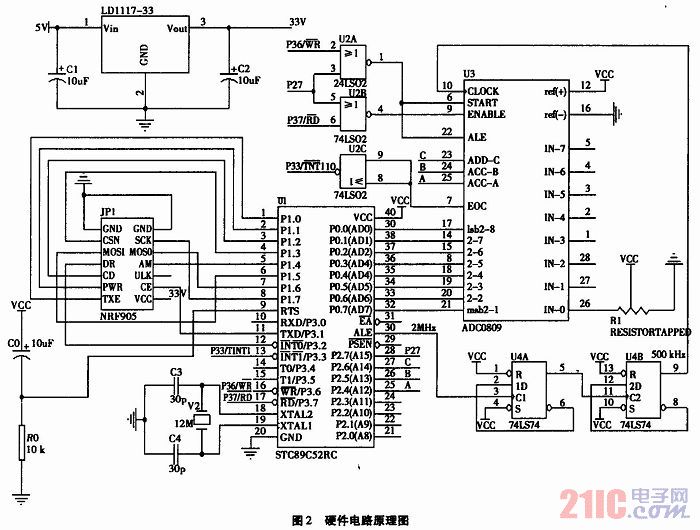
The technology of data acquisition is an important branch of information science. It is not only employed in intelligent instruments but is also widely used in modern industrial production and military science. This technology is essential for process control,...
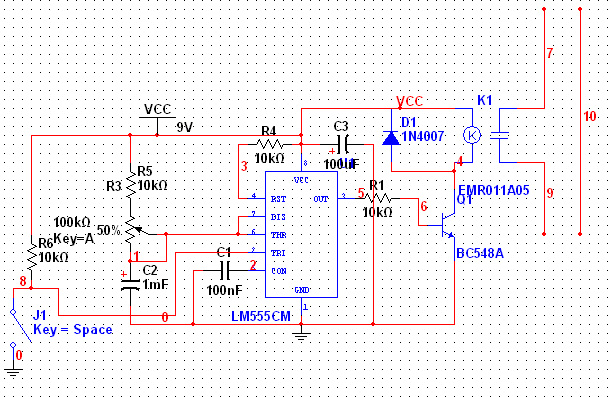
The 555 Timer has extensive applications in electronics. This document describes the use of the 555 Timer in a monostable multivibrator configuration to trigger a transistor driver that energizes a relay, which in turn operates a 230V AC lamp...
You have read about computerized rooms or seen home automation products advertised in electronics magazines. You have decided to try it yourself. However, it is important to note that this project is not inexpensive. A computer is required, which...