
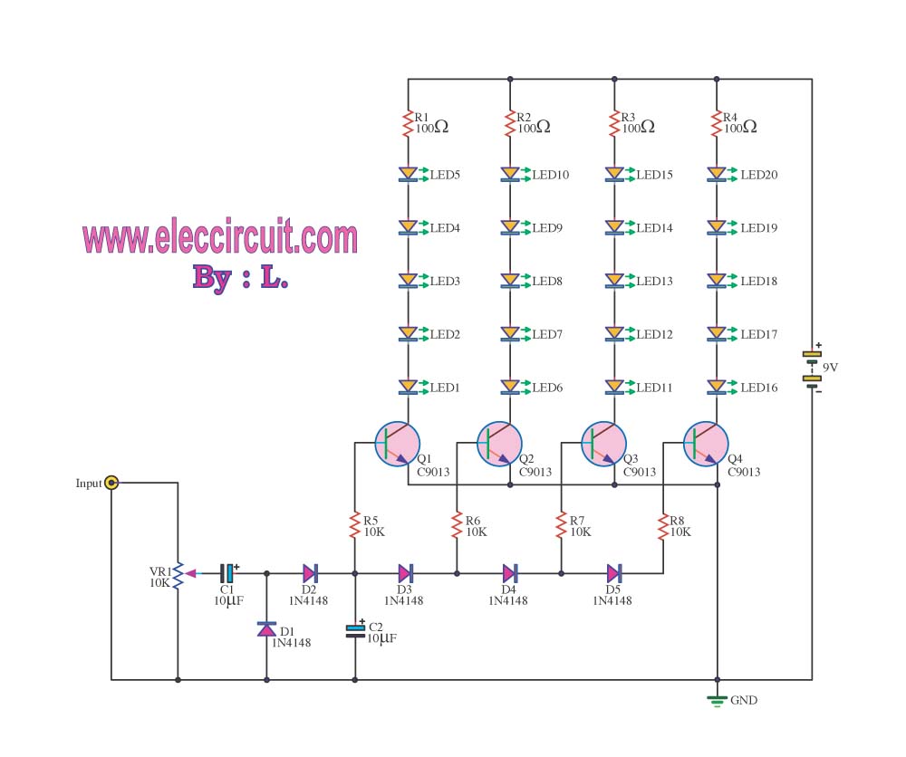
Stress self-test circuit

The schematic features a simple yet effective design for monitoring skin resistance through electric pressure changes. The two contact pads serve as electrodes that measure the voltage drop across the skin, translating this into a corresponding LED indication. The circuit is powered by a 5V supply, which is a standard voltage for many electronic components, ensuring compatibility and ease of integration.
The operation begins when the contact pads make contact with the skin, allowing for a small current to flow. This current generates a voltage drop, which is sensed at the input of the circuit. A comparator or an operational amplifier can be employed to compare the input voltage against predefined thresholds. In this case, the thresholds are set at 150 mV and 650 mV, corresponding to the activation points for LED1 and LED5, respectively.
The output stage of the circuit likely consists of a series of transistors or MOSFETs that drive the LEDs. Each LED is connected in parallel to the output of the driving circuit, ensuring that as the voltage increases, the appropriate transistor is activated to illuminate the corresponding LED. This visual feedback mechanism provides an intuitive way to monitor changes in skin resistance, which can be useful in various applications, including medical diagnostics and biofeedback systems.
In summary, this circuit effectively demonstrates the relationship between skin pressure changes and electrical signals, using a straightforward LED indication system to visualize these changes. The use of low voltage and simple components makes this circuit both safe and accessible for experimentation and educational purposes.Circuit works: two self-test table contact pads sensed across the skin to the electric pressure changes lC input of 5 feet, can drive 10 LED (present circuit only with 5 LED). When the voltage is 5 feet 150 mV, LED1 light; when the voltage elevated to 650 mV, LED5 light.
Related Circuits
The VU meter operates in conjunction with the integrated amplifier circuit. The audio signal is processed by the audio amplifier circuit, which drives the VU meter to display the audio level. The VU meter circuit is designed to visually represent...
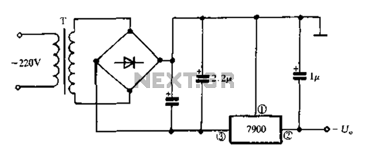
7900 series three-terminal fixed negative output voltage regulator circuit The 7900 series comprises a range of three-terminal fixed negative voltage regulators designed to provide stable output voltages. These regulators are specifically engineered to deliver a consistent output voltage, which is...
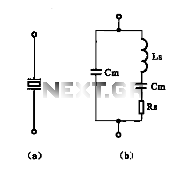
The crystal equivalent RLC circuit is illustrated. The RLC circuit can operate in either a series resonant or parallel resonant configuration. The crystal equivalent RLC circuit is a fundamental electronic circuit that models the behavior of a crystal oscillator. This...
A capacitance meter is an essential instrument for electronics hobbyists and professional electronic technicians. A capacitance meter is a specialized device designed to measure the capacitance of capacitors in various electronic circuits. It typically features a digital or analog display...
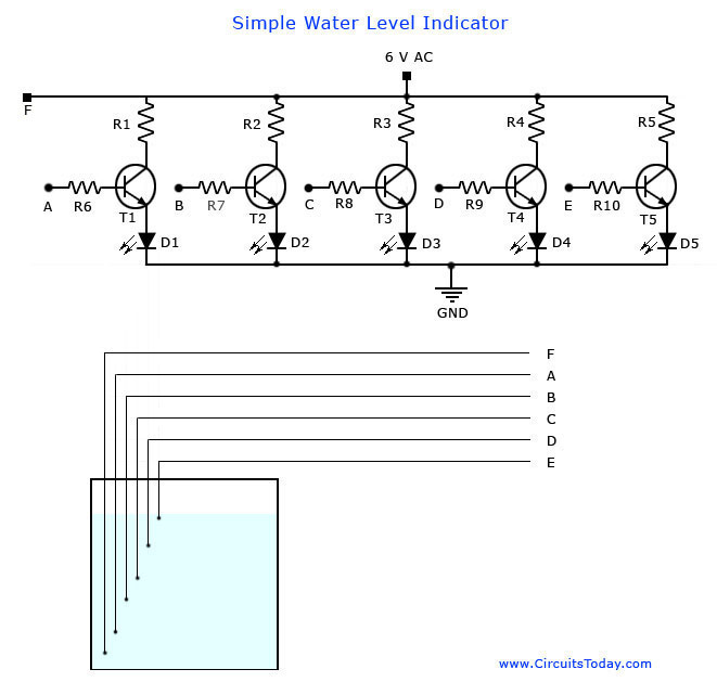
A simple water level indicator project with a circuit diagram for home and industry. This water tank level sensor can be utilized for any liquid level indicator projects. The water level indicator circuit is designed to monitor and display the...
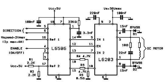
The L620x is a monolithic full bridge switching motor driver implemented using the new Multipower-BCD technology. This technology enables the integration of multiple isolated DMOS power transistors along with mixed CMOS/bipolar control circuits. The L620x series includes various versions:...