
The proximity switch circuit with integrated magnetic field sensor HMC1001
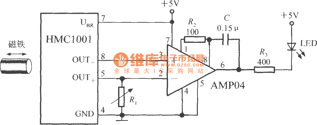
The proximity switch circuit utilizes the HMC1001, a highly sensitive magnetic sensor, which detects the presence of a magnetic field. The operational amplifier (AMP04) is configured in a comparator mode to compare the output voltage from the HMC1001 with a reference voltage.
In this configuration, when the magnet is positioned within the specified range (6mm to 12mm) of the HMC1001, the MR bridge generates an output voltage of 30mV. This voltage is sufficient to exceed the threshold set by the operational amplifier's reference input, resulting in a change in the output state of the comparator. The output of the operational amplifier can then drive an LED, indicating the detection of the magnetic field.
The circuit may include additional components such as resistors to set the reference voltage and capacitors for stability and noise filtering. The LED serves as a visual indicator, illuminating when the magnetic field is detected, providing a clear and immediate response to the presence of the magnet. This circuit is applicable in various automation and sensing applications, where proximity detection is essential for system operation.As shown in figure, the proximity switch circuit is composed of HMC1001, operational amplifier (AMP04) and light emitting diode (LED). The operational amplifier is used as a comparator. When you move magnet with length being 6mm~12mm to HMC1001 in a predetermined position, the output voltage of MR bridge will reach 30mV, then the comparator flips, and output..
🔗 External reference
Related Circuits
An affordable electronic device useful for demonstrating electrostatic phenomena. Ahern's instrument serves as an effective substitute for the tonal electrostatic voltmeter. It provides polarity-dependent information about electric charge motion that conventional instruments do not offer. This apparatus is easy...

This circuit was designed by Lazar Pancic from Yugoslavia. A typical PC sound card includes a microphone input, speaker output, and occasionally line inputs and outputs. The microphone input is specifically tailored for dynamic microphones with an impedance range...
U1 is a 3817 integrated circuit produced by Fairchild Corporation. It is capable of directly driving a display and can operate in both 12-hour and 24-hour formats. Additionally, it can generate a clock sound and activate radios at scheduled...

This circuit regulates a DC power output and has a wide range of applications. It can be utilized to control the speed of a motor, a pump, a toy train, or the brightness of an LED or lamp. Essentially,...

The IR Theremin hardware schematic is notably simple, as the primary input and output devices require minimal connections. This simplicity can be a double-edged sword, as fewer hardware components often lead to increased software complexity. The main components utilized...

The simplest polarity protection technique is to connect a series diode to the power line input. The diode conducts only when the power supply is connected correctly. A series diode is an effective method for preventing reverse polarity in electronic...
Warning: include(partials/cookie-banner.php): Failed to open stream: Permission denied in /var/www/html/nextgr/view-circuit.php on line 713
Warning: include(): Failed opening 'partials/cookie-banner.php' for inclusion (include_path='.:/usr/share/php') in /var/www/html/nextgr/view-circuit.php on line 713