
subwoofer filter circuit

The active subwoofer filter circuit employs a Bessel filter design, characterized by its smooth phase response and minimal group delay, making it particularly effective for audio applications. The cutoff frequency of 200 Hz is strategically chosen, as it separates the low-frequency signals intended for the subwoofer from the higher frequencies that are better suited for satellite speakers.
The buffering stages provided by op-amps A1 and A2 enhance signal integrity, ensuring that the audio signals from the left and right channels are accurately represented without distortion. The high-pass filter sections, comprised of op-amps A2/A4 and A9/A10, effectively remove unwanted low-frequency noise, thereby safeguarding the performance of the satellite speakers. The outputs from these filters are then forwarded to the amplifiers driving the satellite speakers, ensuring that only the appropriate frequency range is amplified.
The integration of both high-pass and low-pass filters within this circuit allows for seamless crossover between the subwoofer and satellite speakers. The low-pass filter, implemented with op-amps A6 and A7, ensures that only the desired low-frequency signals are directed to the subwoofer, while op-amp A8 amplifies this signal for optimal output.
The circuit's design requires a symmetrical power supply to maintain operational stability across the various op-amps. The choice between JFET or bipolar input op-amps allows for flexibility in component selection based on the desired performance characteristics, such as input impedance and noise levels.
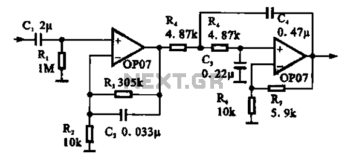
Overall, this active filter circuit is an effective solution for managing audio signals in a subwoofer system, allowing for an enhanced listening experience by optimizing the distribution of sound frequencies across multiple speaker types.This is a circuit of subwoofer active filter circuit is a 24 dB octave filter with a Bessel character and cutoff frequency of 200 Hz. So, if you are interested in experimenting with audio circuits in subwoofer range, this circuit is for you.
This is the figure of the circuit; In subwoofer range, all audio frequencies below 200 Hz can be fed to a s ingle speaker box since the human directional perception of sound diminishes at this frequency range. The normal stereo signals above 200 Hz can be fed to two satellite speaker boxes. How does the subwoofer filter works: A1 and A2 buffer the signals coming from right and left channels.
Op amp combinations A2/A4 and A9/A10 function as the high pass filters. The outputs are then connected to the final amplifiers of the battelite boxes. Signals from both channels are fed to A5. Op amps A6/A7 function as the low pass filter, A8 as the output amplifier for the subwoofer signal. The signal level can be balanced between the subwoofer and the satellite lines. The power needed for this filter circuit must ne a symmetrical power supply. The op amps can have either JFET or bipolar inputs. 🔗 External reference
Related Circuits
This circuit is not highly critical and can utilize various devices (such as a tape player with a message recorded on an endless tape) that do not overload the circuit or the telephone line. The incoming line is safeguarded...
This intelligent electronic lock circuit is constructed using only transistors. To unlock this electronic lock, the user must press tactile switches S1 through S4 in sequence. For added security, these switches can be labeled with different numbers on the...
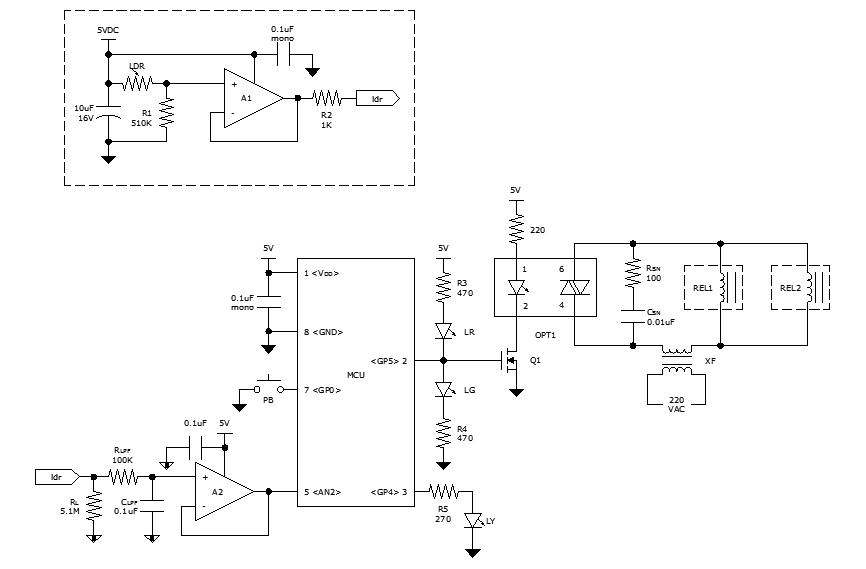
While discussing an all-linear automatic night light circuit, it was mentioned that an MCU-based Automatic Night Light Controller (ANLC) was being tested. The firmware has been tweaked since then. Recently, the sensor was installed outdoors and connected to control...
The car parking sensor circuit utilizes a photodiode as the distance sensor. It measures the distance between adjacent sensors. The car parking sensor circuit employs photodiodes to detect the proximity of obstacles, enhancing parking safety and convenience. Photodiodes are semiconductor...
This circuit is beneficial for applications where a load must be activated from one location and deactivated from another. Multiple momentary normally open (N/O) switches or push buttons can be connected in parallel. The circuit described facilitates remote control of...
Broadband 0.1 to 10 Hz filter amplifier. The broadband circuit consists of two operational amplifiers configured as filter amplifiers operating in the frequency range of 0.1 to 10 Hz. The broadband filter amplifier circuit utilizes two operational amplifiers (op-amps) to...