
auto answering circuit
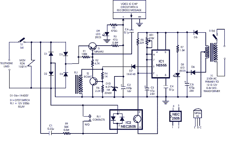
The described circuit serves as a telephone answering device that employs various electronic components to detect incoming calls and relay a pre-recorded message. The protection of the incoming line is achieved through the use of a metal-oxide varistor, which safeguards against voltage surges. The bridge configuration of diodes ensures correct polarity, allowing for reliable operation of the circuit.
The use of the MPSA92 transistor as an electronic switch is critical for interfacing with the telephone line, allowing for the control of the voice message playback. The NE555 timer, configured as a monostable flip-flop, plays a pivotal role in timing the duration of the message playback, ensuring that the message is transmitted effectively without overlap or interruption.
The incorporation of an opto-coupler for ring detection provides electrical isolation between the telephone line and the control circuitry, enhancing safety and reliability. The circuit's design allows for flexibility, enabling the substitution of components based on availability, which is beneficial for prototyping and practical applications.
Overall, this circuit exemplifies a robust design for a telephone answering system, utilizing standard electronic components to achieve functionality while allowing for modifications and testing with various audio sources. The careful consideration of component selection and circuit configuration ensures reliable performance in a range of operational scenarios.This is not very critical and any other device (such as tape player with message recorded on an endess tape) which does not overload the circuit or the telephone line, may be used. The incoming line is protected by metal-oxide varistor (MOV) RDN 130/14 followed by polarity guard circuit comprising diodes D1 through D4 in bridge configuration.
Tran sistor T1 (MPSA92), having a high breakdown voltage (Vce max. ) is used as electronic switch/telephone line interface. It is controlled by transistor T2. Ring detector section comprises capacitor C1, resistor R10 and opto-coupler NEC 2505. (In case of its non-availability, one may substitute it with MC2TE or a similar opto-coupler with additional diode 1N4148 placed with its cathode connected to pin 1 and anode to pin 2 of the opto-coupler. ) Timer NE555 (IC1), configured as monostable flip-flop, is powered by external 230V AC via transformer X1, rectifier diodes D5, D6 and filter capacitor C5.
When switch S1 is on, the incoming telephone line as well as transformer X1 get connected to the circuit and D8 LED lights up. Normally the monoshot IC1 is off (output at pin 3 is low) and so also are the transistors T1, T2 and relay RL1.
When ring is received, the opto-coupler operates and takes trigger pin 2 of timer from high-to-low potential, thereby triggering it. This causes the output at pin 3 of IC1 to go high, which causes relay RL1 to energise and create a bypass for the ringing voltage to the opto-coupler as transistor T2 also gets forward biased.
Conduction of transistor T2 causes forward biasing of switching transistor T1. This, in turn, causes the positive votage from rectifier diodes D3, D4 cathode junction to be extended to voice IC chip after being limited to steady 6. 2 volts by resistor R3, zener D10 and capacitor C2. As a consequence, the voice IC operates and feeds the voice message into the telephone lines via capacitor C6, base-emitter junction of transistor T1 and polarity guard bridge.
The pulse width of timer monoshot (decided by in-circuit value of potentiometer VR1 and capacitor C6) is so adjusted to cover the period of the voice message. At the end of the mono period relay RL1 de-energises and the circuit returns to its original condition.
In this circuit about 100 mA is catered for the voice IC. The circuit can be easily modified (such as by use of DPDT relay etc) for operation with different answering devices. For testing the circuit you may use a musical COB IC. its perfect circuit. while using computer sound use audio driver transformer to isolate PC`s sound card from circuit since 50v pulse of telephone line may damage the sound card
🔗 External reference
Related Circuits

This battery level indicator features five LEDs that illuminate progressively as the voltage increases: Red indicates power connection (0%), Yellow signifies voltage greater than 10.5V (25%). The battery level indicator circuit utilizes a series of five light-emitting diodes (LEDs) to...
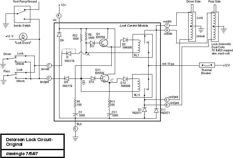
This document discusses the enhancement of a lock control module, providing instructions and photographs for upgrading the module to minimize its standby current consumption, thereby extending battery life. It is assumed that the user possesses a basic level of...
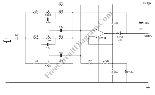
This is a 3 Band Equalizer circuit designed to control the treble, midrange, and bass frequencies. The circuit utilizes a single operational amplifier (op-amp). The 3 Band Equalizer circuit serves to enhance audio signals by allowing users to adjust specific...
To achieve optimal audio reproduction at varying listening levels, it is essential to adjust tone control settings to align with the established characteristics of human auditory perception. The sensitivity of the human ear changes non-linearly across the entire audible...
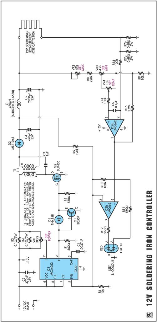
One reason commercial soldering stations are costly is that they typically require soldering irons with built-in temperature sensors, such as thermocouples. This circuit removes the necessity for a specialized sensor by detecting the temperature of a soldering iron heating...
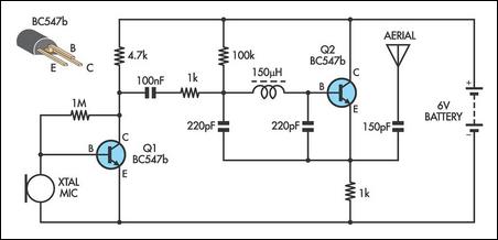
This AM transmitter is designed for simplicity, featuring an untapped inductor with a single winding. The inductor can be easily sourced as a standard RF choke, such as the Jaycar Cat LF-1536. To minimize the circuit size, a conventional...