
Successive approximation a-d converter
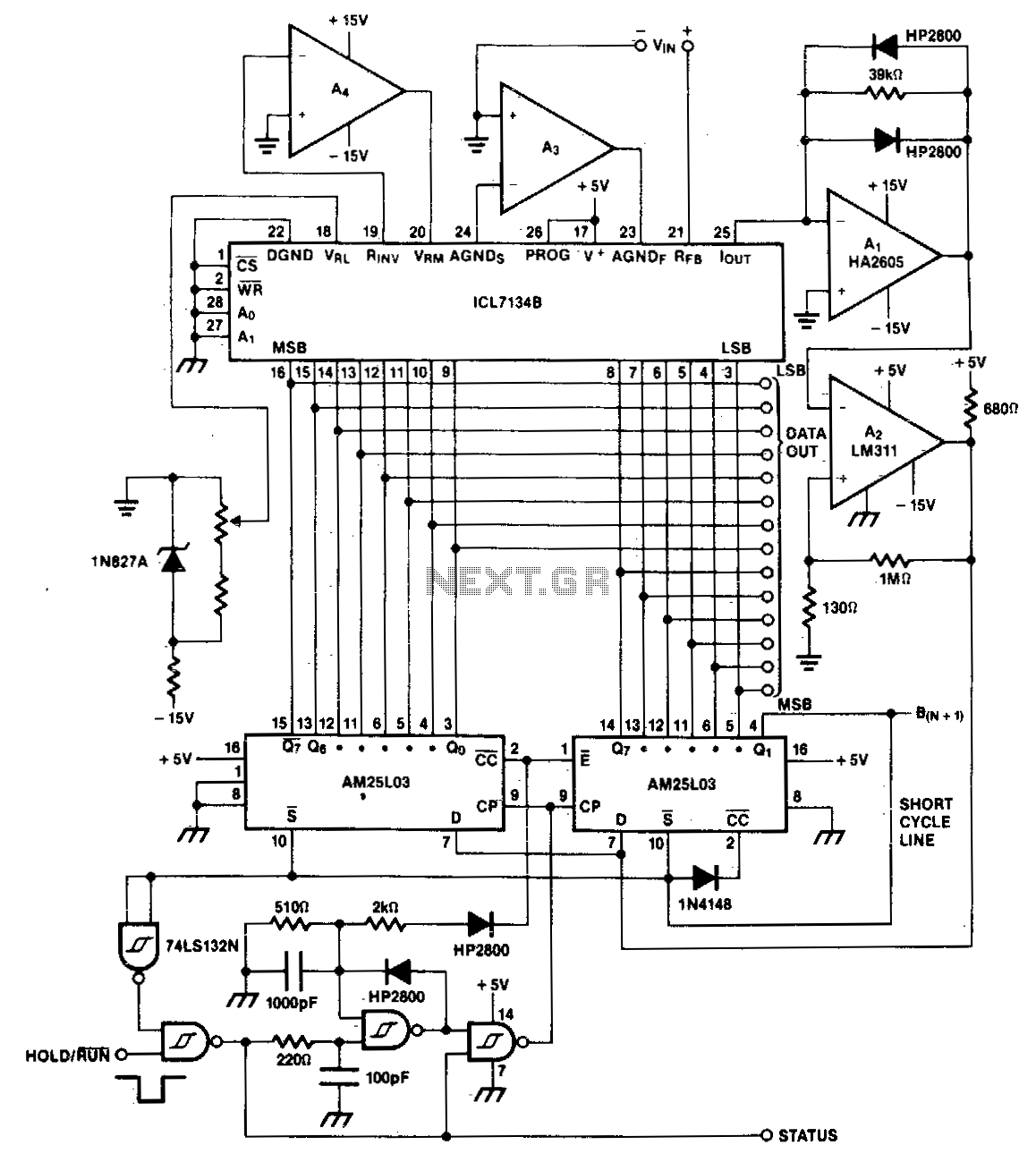
The described A/D converter circuit is designed to achieve high-speed conversion of bipolar signals into a digital format with a resolution of 14 bits. The two AM25L03 components operate in tandem to implement the successive approximation technique, which iteratively narrows down the input signal's digital representation. This method is known for its efficiency in achieving high accuracy with relatively low power consumption.
The comparator's two-stage architecture enhances performance by allowing the HA2605 front-end amplifier to effectively manage the input signal's characteristics before it reaches the decision-making stage of the conversion process. This arrangement is critical for addressing settling time challenges, which can adversely affect the accuracy and speed of the conversion. By reducing the settling time at the summing node, the circuit ensures that the input signal stabilizes quickly, allowing for more rapid successive approximations and thereby increasing the overall throughput of the A/D converter.
Offset nulling is a crucial calibration step for the HA2605 amplifier, as it ensures that any inherent voltage offsets do not introduce errors into the conversion process. This adjustment is vital for maintaining the integrity of the signal being processed, particularly in high-precision applications where even minute discrepancies can lead to significant deviations in the output data.
Overall, this A/D converter design exemplifies a sophisticated approach to high-speed analog-to-digital conversion, leveraging advanced components and careful circuit design to optimize performance and accuracy.A bipolar input, high speed A/D converter uses two AM25L03s to form a 14-bit successive approximation register. The comparator is a two-stage circuit with an HA2605 front-end amplifier used to reduce settling time problems at the summing node
Careful offset-nulling of this amplifier is needed. 🔗 External reference
Related Circuits
The TLD 5085EJ is a smart LED buck converter featuring an integrated power switch, designed to drive a load current of up to 1.8A with excellent line and load regulation. This device is specifically intended for stepping down input...
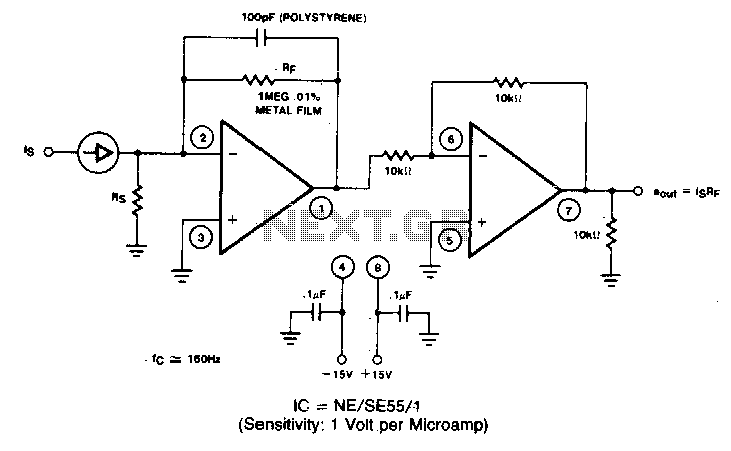
A filter removes the DC component of the rectified AC, which is then scaled to RMS. The output is linear from 40 Hz to 10 kHz or higher. The described circuit primarily consists of a filter designed to eliminate the...
Currently, high-power, high-frequency, narrow pulsing applications primarily utilize vacuum tubes, such as secondary electron transmitting tubes, discharge gap switches, trigatrons, and hydrogen brake pipes. The main research focus is on improving the switching speed of these vacuum devices, aiming...
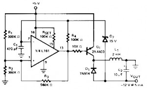
A regulated DC to DC converter utilizing the Micro Power Quad Comparator L161 integrated circuit, which features ultra-low power consumption. This circuit is designed to convert 5V DC to 12V DC at a current output of 5mA. The circuit employs...
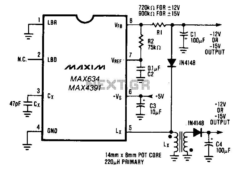
The buck-boost configuration of the MAX634 is well suited for dual output DC-DC converters. Only a second winding on the inductor is needed. Typically, this second winding is bifilar; the primary and secondary are wound simultaneously using two wires...
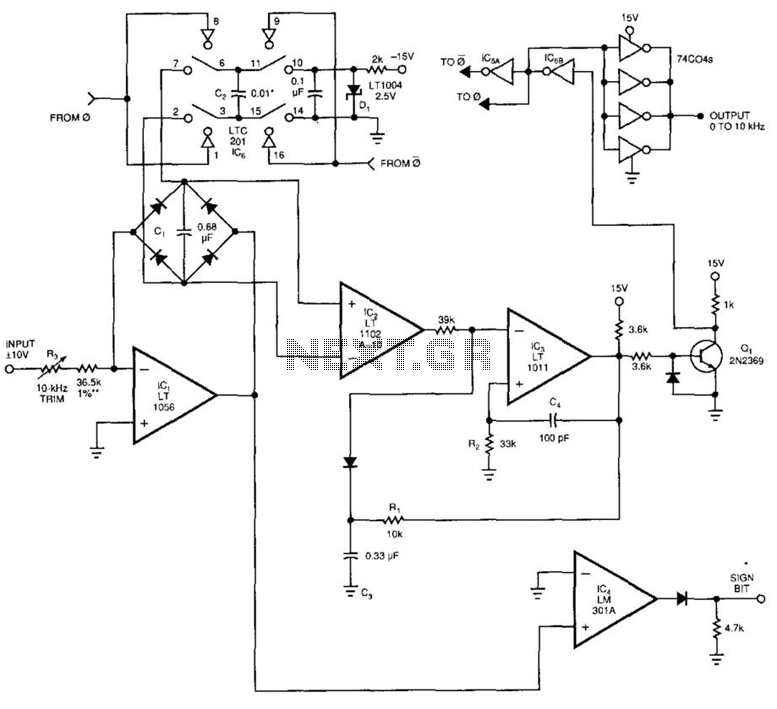
This voltage-to-frequency converter (VFC) accepts bipolar AC inputs. For -10 to +10 V inputs, the converter produces a proportional 0 to 10 kHz output. Linearity is 0.04%, and the temperature coefficient (TC) is approximately 50 ppm/°C. To understand the...