
Summing CT Measurements

The circuit design incorporates several critical components to ensure accurate measurement and functionality. The operational amplifier is configured in an inverting summation mode, allowing multiple input currents from the CTs to be summed effectively. Each CT is connected to the op-amp's input, and the feedback resistor is chosen based on the required output voltage range. The use of zener diodes in the CTs provides protection against high voltage spikes, ensuring safe operation. Additionally, the inclusion of resistors and capacitors for EMC protection helps minimize interference and maintain signal integrity. The output of the circuit, being phase-inverted, necessitates careful installation of the CTs to ensure accurate readings. The overall design aims to achieve a reliable and efficient method for monitoring electrical parameters across various distribution points while addressing the challenges associated with current measurement.This could be achieved by monitoring separate points either through the same recorder, or worse still, two separate recorders. In both cases the results need to be artificially summed to get the total current draw. Two problems exist with this, the first being the actual VA, VAR, kW, etc cannot be measured as "inter distribution point" currents ar
e not taken into account. The ideal solution would be to have the selected distribution points all supplied from one common supply, or at least all the required phases available for common clamping in one CT in order to affect measurement. This is not always practical. Wiring CTs in series, each CT with it`s own termination resistor, will only apply if the input to the recorder is greater than 1000 times the sum of all the termination resistors, this is usually an impractical figure.
Wiring in parallel requires that the recorder has a near zero resistance input, this not being the norm as most fix-on or clamp-on CTs output a voltage relative to the measured current. Wiring either in series or parallel also creates a further complication if certain CTs need to be taken out of circuit.
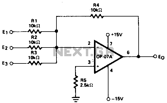
The circuit is a simple current to voltage converter. In this configuration the op-amp will always try to ensure the negative input (pin 2) remains equal in voltage to the positive input (pin 3). Ignoring CT inputs 2 through 4, if a current of +1mA was introduced on CT input 1 the op-amp would swing it`s output negative by 1 volt to introduce a current of -1mA (1 volt through 1k ©) to counteract the input current and bring pin 2 back to the voltage level of pin 3.
As pin 3 is at ground potential the impedance at pin 2 is therefore 0 ©. If each input were to have +1mA current presented on them the output would now, in order to compensate, be -4 volts i. e. a summation of the inputs. The circuit will be well known to audio buffs (specifically audio mixer designers) as it is typically used as a mixer bus amplifier as, owing to the fact the summation input is effectively a "zero ohms" point, it offers the best inter-input isolation i.
e. input 1 is not affected by anything introduced on input 2 as well as each input is a constant impedance being the input resistor. In our case this allows individual CTs to be disconnected as required, with no effect on the remaining devices connected.
The 10 ohm resistors and 330pF capacitor are EMC protection components and do not affect the accuracy of the summing circuit. The only factor to be borne in mind is the output is inverted in phase to the input, this is counteracted by reversing the CTs on installation.
There are a range of CTs available from Sentran Corporation and are ideally suited to this application. They are available with ratios of 1000:1, 2000:1, and 3000:1. The CTs are also fitted with zener diodes that ensure the output does not generate a high voltage when disconnected from the summing amp (a known problem with CTs), They do not affect the accuracy when the CT is connected as there is effectively no output voltage and the zeners therefore do not conduct.
In our example using the 1:2000 ratio would result in 1mA on the input for every 2A measured, or 2. 5mA for 5A (the full scale of the smallest available CT). This would result in an output of 1V and 2. 5V respectively. By choosing the correct ratio and feedback resistor the desired range can be achieved. It is not advisable to have a feedback resistor of lower than 500 © or greater than 5k ©. The saying "Practice Disproves Theory", a statement known by many engineers, had some relevance here too! As always what is planned for very seldom happens when everything is assembled. There were some surprising results. We had a slight phase shift (expected) which was leading in phase (unexpected - remember, we`re dealing with inductors) but this increased with using the CT in the usual "current to voltage" mode (very unexpected).
Quickly explained, 🔗 External reference
Related Circuits
This circuit generates continuous outputs that depend on multiple input variables. The circuit in question typically employs a combination of operational amplifiers (op-amps), resistors, and potentiometers to achieve its functionality. The outputs can be tailored based on the variations...
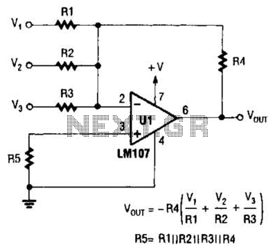
The output of Ul is the sum of Vv, multiplied by the ratio of Rx to Rv, RJRV, and respectively. Resistors R1, R2, and R3 are selected as required for individual gains. Additionally, R4 influences the gain of all...
It is often challenging to measure the current in the positive lead of a power supply, such as a battery charger. Fortunately, specialized integrated circuits (ICs) have been developed for this purpose in recent years, including the Burr-Brown INA138...
A request to build an analog summing amplifier, preferably utilizing vacuum tubes to achieve the characteristic tube sound. An analog summing amplifier is a circuit that combines multiple input signals into a single output signal. The use of vacuum tubes...
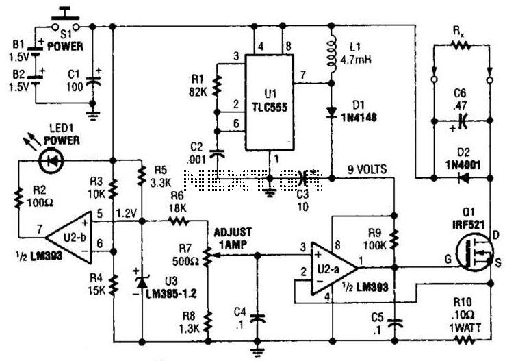
Useful for low-resistance measurements, this 1-A current source will produce 1 A in unknown resistance Rx. For best results, Rc should be less than 1 to 2, because only 3 V are available. Ul is a flyback converter to...
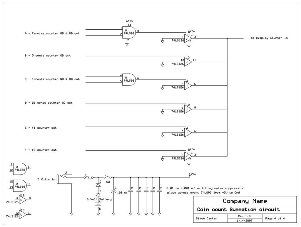
The outputs of all coin counters are summed in a 74LS126 tri-state buffer, which is used to connect all the counter outputs to the input. The circuit utilizes a 74LS126, a quad buffer/driver with three-state outputs, to manage the outputs...