
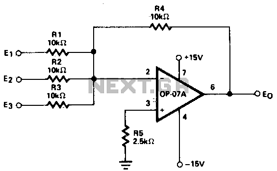
Adjustment-free precision summing amplifier
The circuit in question typically employs a combination of operational amplifiers (op-amps), resistors, and potentiometers to achieve its functionality. The outputs can be tailored based on the variations in the input variables, which may include voltage levels or other analog signals.
In a typical configuration, multiple input signals are fed into a summing amplifier configuration, where each input is weighted according to its respective gain set by the resistors. The output of the summing amplifier is then processed through further stages, which may include filtering and amplification, to ensure that the output signal is stable and meets the desired specifications.
For instance, if the circuit is designed to respond to three different input variables, each input would be connected to a dedicated resistor that sets the gain for that particular input. The summing junction of the op-amp will combine these inputs, and the output can be monitored or utilized for further processing.
Additionally, the circuit might incorporate feedback mechanisms to enhance stability and linearity of the output. This could involve using negative feedback to minimize distortion and improve the overall performance of the circuit.
In summary, this circuit effectively translates multiple input variables into a continuous output through careful design and integration of various electronic components, ensuring reliable operation in various applications.This circuit produces continuous outputs that are a function of multiple input variables. Circuit shown 🔗 External reference
Related Circuits
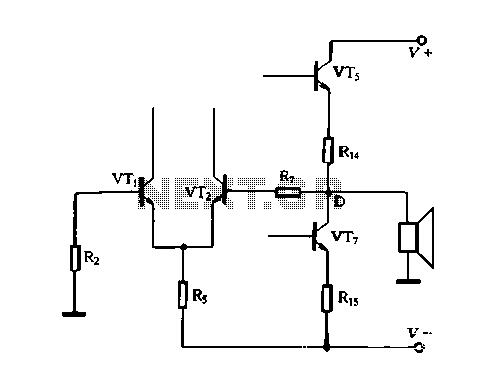
The DC feedback circuit is illustrated in Figure 1-31. In this circuit, resistor R7 is connected to the output terminal, which is the midpoint of the static differential input stage voltage Vr, between the base terminals. This configuration represents...
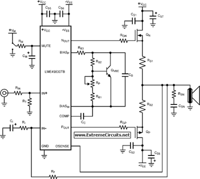
The LME49830 EF125WT1 amplifier PCB module features National Semiconductor's LME ultra-high fidelity power amplifier input stage integrated circuits (drivers). The LME49830 is a fully complementary bipolar 200V input stage IC with a typical output current of 56mA, specifically optimized...
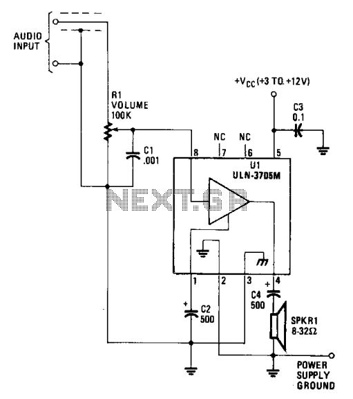
The amplifier functions with supply voltages up to 12 volts and can operate at lower voltages as low as 1.8 volts while maintaining acceptable distortion levels, albeit with reduced volume. Its power requirements make it suitable for applications powered...
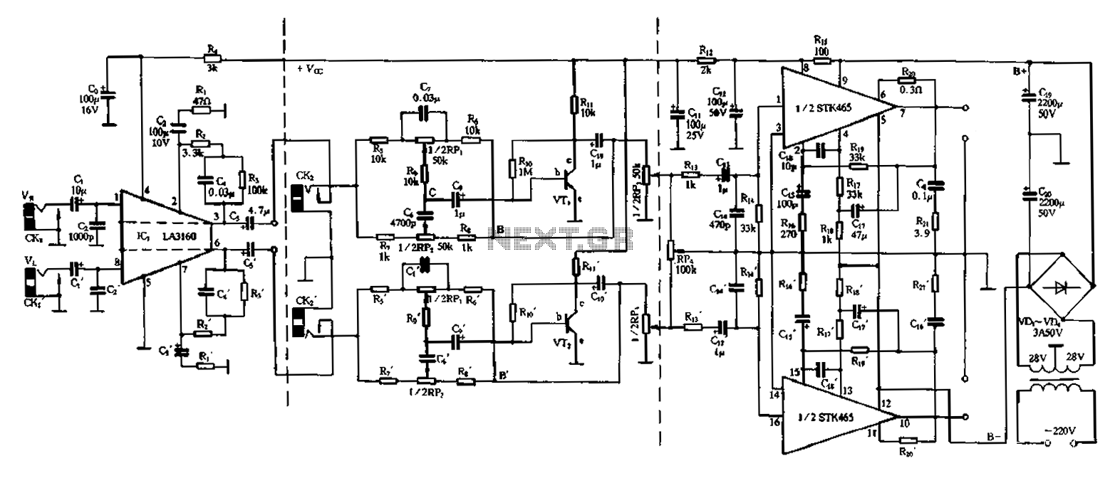
The 50W is a two-channel amplifier featuring a preamplifier and tone control based on the LA3160 integrated circuit. Its external components include the input preamplifier, with C1 serving as the input coupling capacitor. The circuit incorporates a high-frequency bypass...
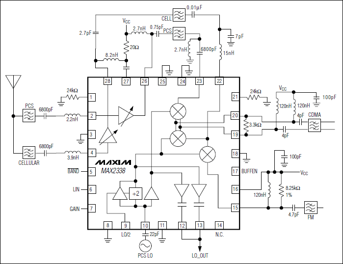
The MAX2338 receiver RF front-end integrated circuit (IC) is tailored for dual-band CDMA cellular phones and is also applicable in dual-band TDMA, GSM, or EDGE cellular phones. The integrated low-power local oscillator (LO) divider allows for the elimination of...
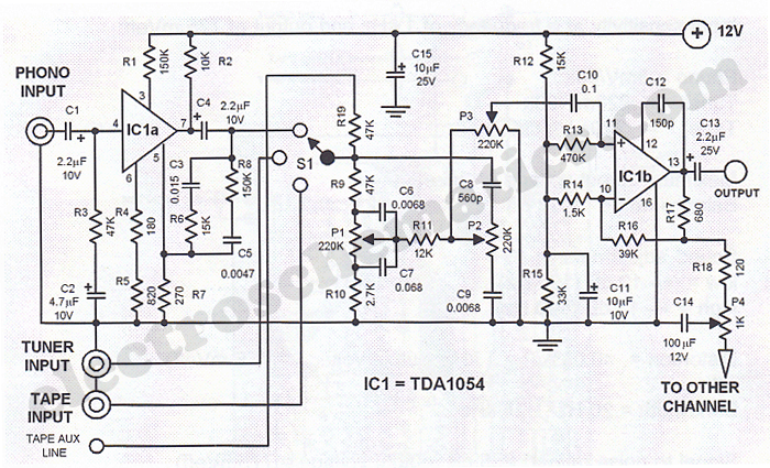
This Hi-Fi stereo preamplifier circuit is designed using the TDA1054 integrated circuit from SGS. The TDA1054 is a 16-pin DIL package that incorporates two separate preamplifier circuits. It is a low-noise preamplifier with minimal complications in the design process....
Warning: include(partials/cookie-banner.php): Failed to open stream: Permission denied in /var/www/html/nextgr/view-circuit.php on line 713
Warning: include(): Failed opening 'partials/cookie-banner.php' for inclusion (include_path='.:/usr/share/php') in /var/www/html/nextgr/view-circuit.php on line 713