
Timer circuit
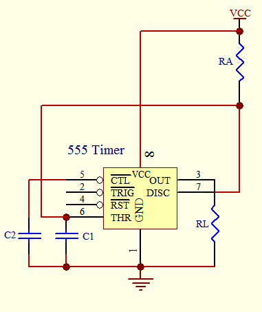
The 555 timer IC is renowned for its versatility in timing applications. In monostable mode, it functions as a one-shot pulse generator, producing a single output pulse in response to a trigger input. The duration of this pulse is determined by the resistor-capacitor (RC) network, where the time period (T) is calculated using the formula T = 1.1 * RA * C1. The charging and discharging of C1 through RA and the internal transistor Tr dictate the pulse width, making it ideal for applications requiring precise timing.
In astable mode, the 555 timer operates as an oscillator, generating a continuous square wave output. The frequency of oscillation is determined by both resistors RA and RB and the capacitor C. The output frequency (f) can be calculated using the formula f = 1.44 / ((RA + 2*RB) * C). This configuration allows for adjustable duty cycles, as the ratio of RA to RB influences the high and low times of the output waveform.
The 555 timer's internal architecture includes comparators, flip-flops, and a discharge transistor, all of which facilitate its operation in both modes. The comparators monitor the voltage levels at the threshold and trigger pins, while the flip-flop controls the output state based on these levels. The discharging transistor Tr provides a path for the capacitor to discharge, thus resetting the timing cycle.
The practical applications of the 555 timer IC extend to a wide range of fields, including automotive systems, industrial controls, and consumer electronics, where precise timing, pulse generation, and sequential operations are required. Its ease of use, combined with the ability to achieve various timing intervals and frequencies, makes the 555 timer an essential component in electronic design.Timer circuit has been used in many projects and there are basically 2 types that are used these days. One of them is the use of analog RC circuit where charging of the capacitor circuit determined the T of the circuitry.
This type of circuitry has larger tolerance and is used in applications where the T is not so critical as the T is affected by the tolerance of the RC components used. The other is the use of crystal or ceramic resonators together with microprocessor, microcontroller or application specific integrated circuit that need higher precision T in the tolerance of up to 5 ppm (parts per million). One commonly used circuit is the 555 IC which is a highly stable controller capable of producing timing pulses.
With a monostable operation, the T(time) delay is controlled by one external resistor and one capacitor. With an astable operation, the frequency and duty cycle are accurately controlled by two external resistors and one capacitor.
The application of this integrated circuit is in the areas of PRECISION TIMING, PULSE GENERATION, TIMING DELAY GENERATION and SEQUENTIAL TIMING. In this mode, the device generates a fixed pulse whenever the trigger voltage falls below Vcc/3. When the trigger pulse voltage applied to pin 2 falls below Vcc/3 while the its output is low, its internal flip-flop turns the discharging transistor Tr off and causes the output to become high by charging the external capacitor C1 and setting the flip-flop output at the same instant.
The voltage across the external capacitor C1, VC1 increases exponentially with the T constant T=RA*C1 and reaches 2Vcc/3 at td=1. 1RA*C1. Hence, capacitor C1 is charged through resistor RA. The greater the time constant RA*C1, the longer it takes for the VC1 to reach 2Vcc/3. In other words, the time constant RA*C1 controls the output pulse width. When the applied voltage to the capacitor C1 reaches 2Vcc/3, the comparator on the trigger terminal resets the flip-flop, turning the discharging transistor Tr on.
At this time, C1 begins to discharge and its output goes to low. An astable operation is achieved by configuring the circuit as shown above. In the astable operation, the trigger terminal and the threshold terminal are connected so that a self-trigger is formed, operating as a multivibrator. When its output is high, its internal discharging transistor Tr turns off and the VC1 increases by exponential function with the time constant (RA+RB)*C.
When the VC1, or the threshold voltage, reaches 2Vcc/3, the comparator output on the trigger terminal becomes high, resetting the F/F and causing its output to become low. This in turn turns on the discharging transistor Tr and the C1 discharges through the discharging channel formed by RB and the discharging transistor Tr.
When the VC1 falls below Vcc/3, the comparator output on the trigger terminal becomes high and the tmr. output becomes high again. The discharging transistor Tr turns off and the VC1 rises again. The frequency of oscillation is given as below. 🔗 External reference
Related Circuits
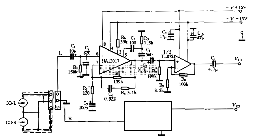
Figure 3-16 illustrates a low-noise preamplifier equalizing circuit using the HA12017. This circuit includes playback components R3, R4, and C4, which conform to a standard balanced network. The gain of the circuit is -7dB at 1kHz, while the output...
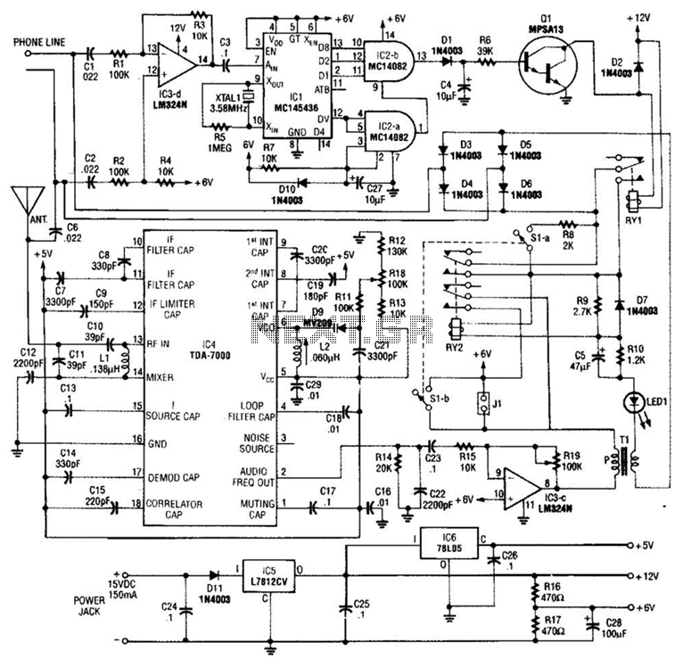
When the asterisk (*) is pressed on the touch-tone phone, a DTMF decoder, referred to as TCI, manages the on-hold logic. Audio from the FM receiver IC4 is transmitted over the telephone line when a hold condition is active....
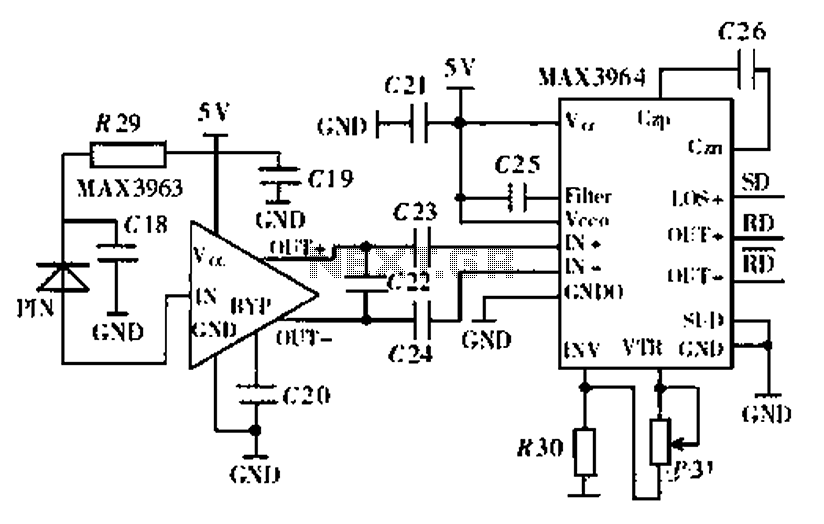
Ethernet is the most widely used networking technology, known for its high reliability, informative media, and ease of expansion and updates. It is commonly utilized in businesses, schools, and various other fields. According to the IEEE802.3 Ethernet specification, the...
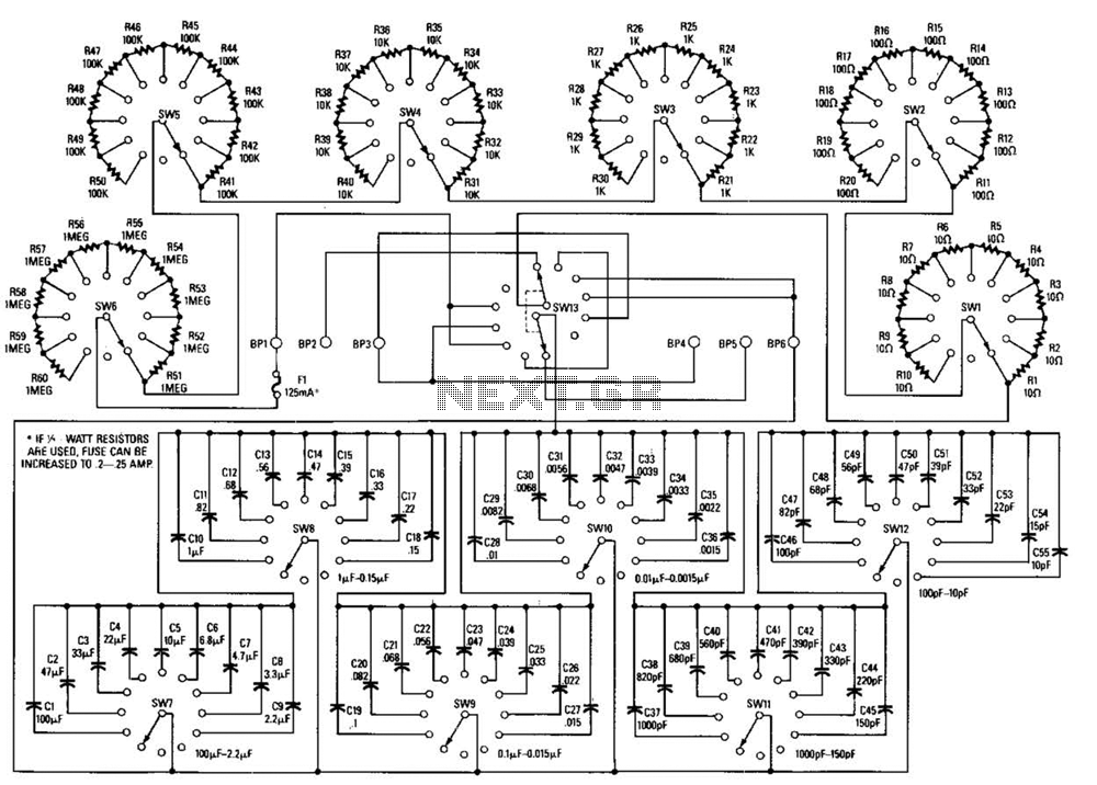
This decade box can be configured for any resistance value between 10 and 11.1 in 10-stop increments. A switch is employed to set various RC configurations. It is recommended to utilize precision components in the circuit. If feasible, verify...
This is a simple game show timer designed for beginners. The power source can be a standard 12-volt lantern battery or a battery pack made from C or D cells. The lamps used can be regular flashlight bulbs; the...
Note: Do not build or use this if you do not have any knowledge in electrical or electronics. This project is not safe for beginners, and the voltage involved is dangerous and can cause electrocution. Do not exceed the...