
supercapacitor usb light
The components required for this project include a 5.5V, 0.1F supercapacitor (sourced from Farnell), a white LED, a 1K Ohm resistor, and a USB male connector (obtained from a broken pendrive). The accompanying schematic diagram provides a complete overview of the circuit. It is permissible to use a supercapacitor with a higher Farad rating, provided the voltage rating is equal to or exceeds 5V. The configuration of the components can be creatively approached. When properly connected, the white LED should illuminate; if it does not, there may be an error in the connections. After 10 to 30 seconds of charging, the supercapacitor can be disconnected, providing approximately 10 minutes of LED illumination.
The circuitry is straightforward; when connected to a PC, the USB port charges the supercapacitor. A 10 Ohm resistor (R1) limits the current from the USB port to a maximum of 500mA (5V/10 Ohm), although this resistor also prolongs the charging time. For larger capacitance supercapacitors, a charging duration of 1 to 2 minutes may be necessary. On the LED side, switch S1 controls the LED's power state, while the 1K Ohm resistor (R2) regulates the current flowing to the LED. Utilizing a lower resistance value for R2, such as 330 Ohms, will enhance the LED's brightness but will also decrease the operating time per charge. Conversely, increasing the resistance value for R2 will extend the operating time while diminishing brightness. A resistance value of 1K Ohm has been identified as an optimal balance between brightness and operating duration.
In this circuit, the charging section remains unchanged, but switches S2 and resistor R3 are incorporated on the LED side. S1 and R2 continue to function as previously described, allowing the LED to operate at 1K Ohm brightness when S1 is activated. The addition of S2 and R3 permits a secondary brightness level; when S2 is engaged, the LED operates at 330 Ohm brightness, resulting in increased brightness due to the reduced current-limiting resistor. This configuration allows for three distinct brightness levels: the first level is achieved with S1, the second with S2, and the third level is reached by activating both S1 and S2 simultaneously, resulting in maximum LED brightness.
This circuit design not only demonstrates the functionality of supercapacitors but also provides a practical application for varying LED brightness through simple resistor and switch configurations. The careful selection of resistor values and the use of switches enable the user to control the LED's brightness according to their preferences, making this project both educational and enjoyable.For those who never heard about supercapacitor, you can check for more info about supercapacitor here. Supercapacitor is basically a capacitor with very high capacity, and the capacity rating is normally around few Farads.
With the super capacity, it basically can store a lot of charge, and I am going to use the super capacity to store charges for a 5mm LED. Let`s see how long will the 5mm LED last. The components you will need for this project is basically a supercapacitor (I am using 5. 5V 0. 1F supercapacitor which I bought from Farnell), a White LED, a 1K Ohm resistor and a USB male connector (I get this from an broken pendrive). Please check the diagram below for the complete schematic. You are actually free to use higher Farad supercapacitor, but voltage rating must be larger or equal to 5V, and you can have your creative way to connect all the components together.
You should see the White LED turned on (if it doesn`t turned on, there are some mistake in the connection), then after 10-30 second, you can unplug it and you should have around 10 minutes of the LED light. The circuitry is simple, when you plug it into PC, the USB port will start charging the Supercapacitor, and there is a 10Ohm resistor (R1) limiting the current from USB port to 5V/10Ohm = 500mA maximum, but the R1 will also slow down the charging time.
For large capacitance Supercap, you might need to let it charge for around 1 to 2 minutes. At the LED side, the S1 will let you turn ON or OFF the LED, and the 1KOhm resistor (R2) is to limit the current for the LED. If you use smaller value for R2, like 330Ohm, it will increase the brightness of LED but will also reduce the operating time of the LED for one charge.
By using larger value for R2, you will increase the operating time, but reducing the brightness. I found 1K to be the balance value for the brightness and operating time. In this circuit, the charging and USB port part is still the same, but I add in S2 and R3 at the LED side. So, the S1 and R2 will still function like the previous one, that by switching on S1, you will get the 1KOhm resistor brightness.
By adding S2 and R3, it means that if you switch on S2, you will get 330Ohm brightness, which is brighter than 1KOhm brightness, because the resistor that limiting the LED current is now smaller and higher current on the LED means higher brightness. I say you will have 3 level brightness, so, the third level brightness is by switching ON S1 and S2 at the same time.
🔗 External reference
Related Circuits
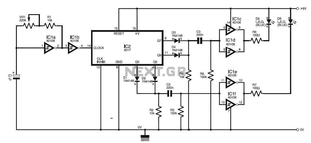
This circuit simulates the flashing strobe lights of British police cars by alternating the lights. The IC1a functions as a square wave oscillator with an adjustable frequency controlled by VR1 to achieve the desired effect. The circuit utilizes an...
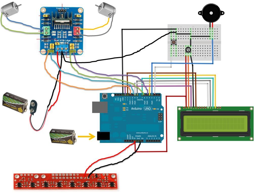
If the robot is positioned on the black line, it will continue moving forward. However, if it veers off the line and enters a white area, it will assess whether to correct its path to the left or right,...
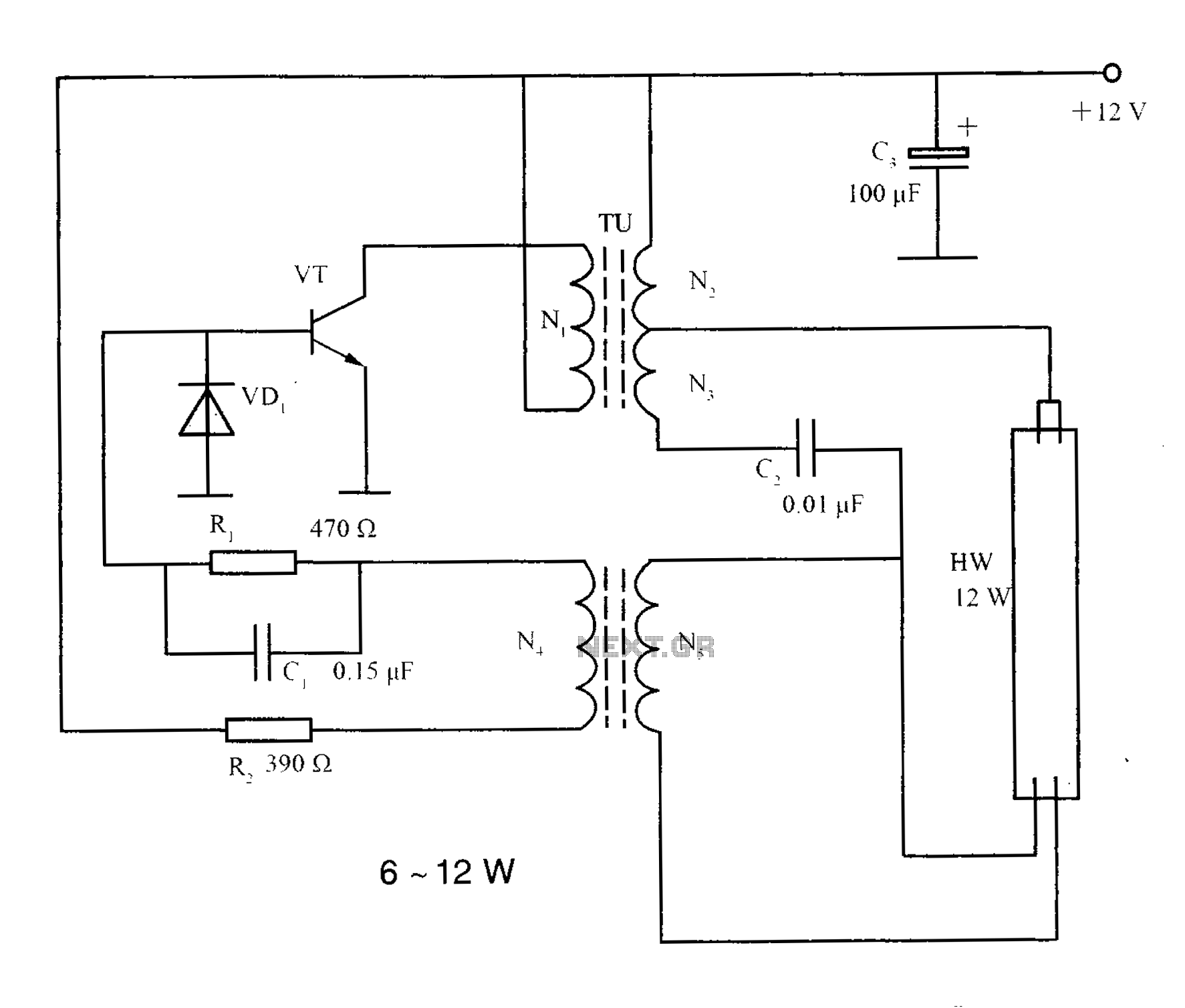
The lighting inverter circuit is designed for 6 to 12W fluorescent lamps. It operates by first bucking the mains voltage, followed by rectification and filtering to charge a battery. When the inverter is activated, it generates a high-frequency alternating...
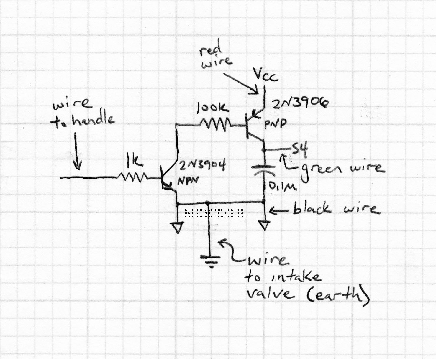
This intelligent electronic lock circuit is constructed using only transistors. To unlock this electronic lock, the user must press tactile switches S1 through S4 in sequence. For added security, these switches can be labeled with different numbers on the...
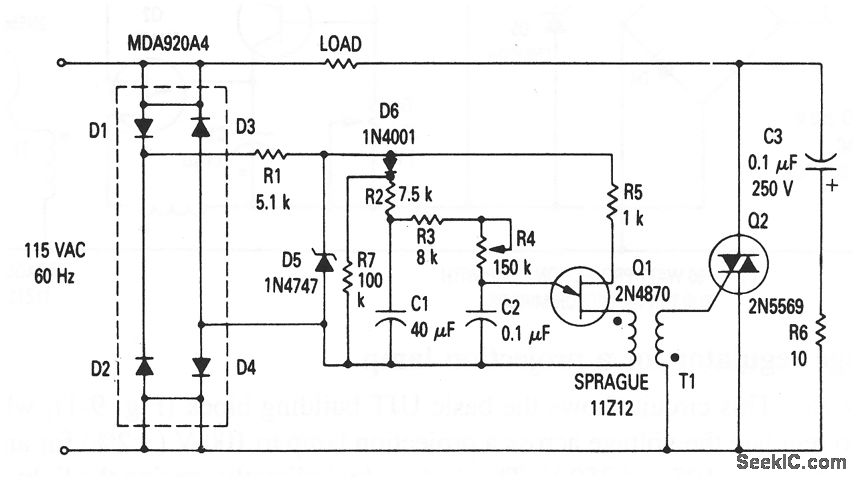
This circuit illustrates the fundamental UJT building block, utilized in a light dimmer with soft-start functionality. It gradually applies current to the light, effectively minimizing high surges (high inrush current) that typically occur in cold-filament light dimmers, which can...
Currently, white LEDs are available that emit a significant amount of light. Their brightness is such that direct eye contact should be avoided. Although they are still relatively expensive, this is expected to change in the future. A highly...