
Superheterodyne Radio Uses One Tube
The design of this radio project incorporates various elements that enhance its functionality and performance. The 6BA7 vacuum tube serves as the primary active device, benefiting from its high gain, which is crucial for effective signal amplification in a superheterodyne configuration. The detector circuit's resemblance to a fixed-frequency crystal set indicates a straightforward yet effective method for demodulating the incoming radio signals.
The Bogen T725 transformer is integral to the design, as it optimizes the impedance matching between the detector diode and the headphones, ensuring that audio output is clear and well-defined. The inclusion of a tap selector switch enhances user convenience, allowing for quick adjustments when switching between different headphone types.
For improved selectivity, the option to replace the Bogen T725 with a transformer that has a higher input impedance is notable. This modification would require adjusting the benny resistor from 18k ohms to approximately 180k ohms, accommodating the lighter load presented to the IF transformer secondary.
The input coil, crafted from HDPE material, demonstrates careful consideration of both physical design and electrical characteristics. The use of 54 turns of 165/46 litz wire indicates an emphasis on minimizing losses due to skin effect, which is particularly important in high-frequency applications. The variable capacitor's interaction with the coil allows for fine-tuning across the desired frequency range, with the trimmer capacitor providing a means to correct any tracking errors that may arise during operation.
The local oscillator, operating at 455 kHz above the incoming signal, is a crucial aspect of the superheterodyne design. The oscillator coil's inductance, calculated to be 98 µH, is essential for ensuring that the circuit functions correctly across the intended frequency range. The careful selection of components and adherence to design principles will contribute to the overall performance and reliability of the radio project, making it a valuable addition to the builder's portfolio of radio designs.Nothing in this project is real original, but I did do a couple of modifications from the circuits I saw. The fellow that started this, as far as I can tell is Jack Bryant, KE4ID with his one tube superhet contest radio project.
That was my basis for this set. I started drawing the circuit. I usually don`t release too many details early in a project but this time is different. I did get some good suggestions from my fellow radio friends, Ben Tongue and Mike Peebles. I had most of the design down but these two fine fellows gave me some extra ideas that were helpful in this design. This radio is built with the One Active Device (1AD) contest in mind. My two previous entries were done with two regenerative contest receivers. My 6SK7 and Acorn sets where the projects. They worked very well. But as time goes on, different ideas have to be tried. Jack and the others reported good results with these radios, especially when operated close to local stations.
I don`t have that problem, but I just had to try it. The central part of this project is the 6BA7 vacuum tube. Using research of others, I decided that due the higher gain over other similar tubes, that this was the way to go. The other major section of this radio is the detector circuit. Looking closely, it looks like a fixed frequency crystal set. That`s what it is alright. The Bogen T725 provides a closer match between the detector diode / IF transformer and the headphones.
An optional tap selector switch was added so that changing headphones would be easier. Better selectivity can be realized if you exchange the Bogen T725 for a transformer for an G berformer. The G berformer has an input impedance 5 times the Bogen and provides a much lighter load to the IF transformer secondary.
The benny resistor (18k) will have to be changed to a higher value, about 180k ohms. The input coil is one of my standard spider web coils with an inductance of about 225 microhenries. I used a spider coil form with a two inch (50mm) hub and a 4-1/2 inch (108mm) outside diameter. The coil is 1/8 inch thick HDPE material. I wound 54 turns of 165/46 litz. The number of turns was based on using a 440 pf variable capacitor. This coil was wound with some extra turns and then during testing, a couple of turns were removed until the entire band plus a tiny bit covered the entire dial. There is a front panel 20 pf trimmer that is used to adjust for any tracking error. In my original design, this adjustment was a screwdriver adjustment. But since tracking isn`t perfect across the dial, this occasional adjustment will keep the radio peaked.
Details of the adjustment of this coil is described below in the alignment section. Another tuned circuit in my superhet radio is the local oscillator. This coil inductance depends mostly on the variable tuning capacitor value. The value of my coil turned out to be 98 µh. This was determined by a handy online superhet oscillator tracking calculator. If you are using somewhat different parts, you are on your own. The accuracy of the tracking is dependant on how close your coil is to the right value. The coil is tapped with the tickler tap meant to be connected to the cathode. Be careful to pick the right coil. The 4 lug coils are sometimes meant for the tickler to be placed in the oscillator triode plate, such as with a 1A7 tube. This type won`t work in this circuit. Since the Intermediate Frequency (IF) is 455khz, the oscillator works always at a frequency 455khz above the incoming signal.
There is atrimmeradjustment capacitor that is wired across the main variable capacitor. Th 🔗 External reference
Related Circuits
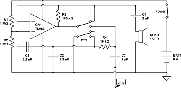
The circuit operates in receive mode, with the Push-To-Talk (PTT) switch enabling transmit mode. The speaker functions as both a microphone and a speaker. Most systems observed utilize a rocking armature transducer for the speaker. There is no base...
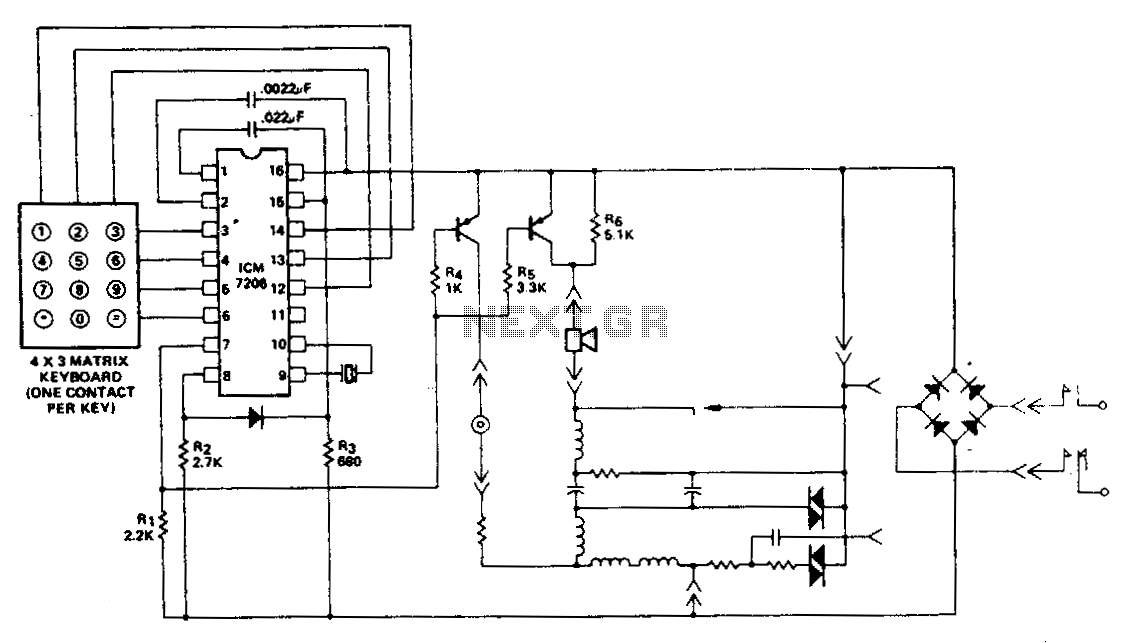
This encoder utilizes a single contact per key keyboard and manages all other switching functions electronically. A diode connected between terminals 8 and 15 limits the output to no more than 1 V negative concerning the negative supply, Vss....
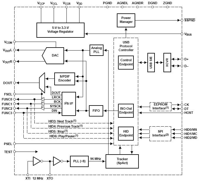
This project involves a high-fidelity external USB sound card or USB headphone system designed for use with PCs or Macs. It utilizes the PCM2706 integrated circuit, which serves as a high-quality, crystal-clear 16-bit stereo digital-to-analog converter (DAC). The PCM2706...
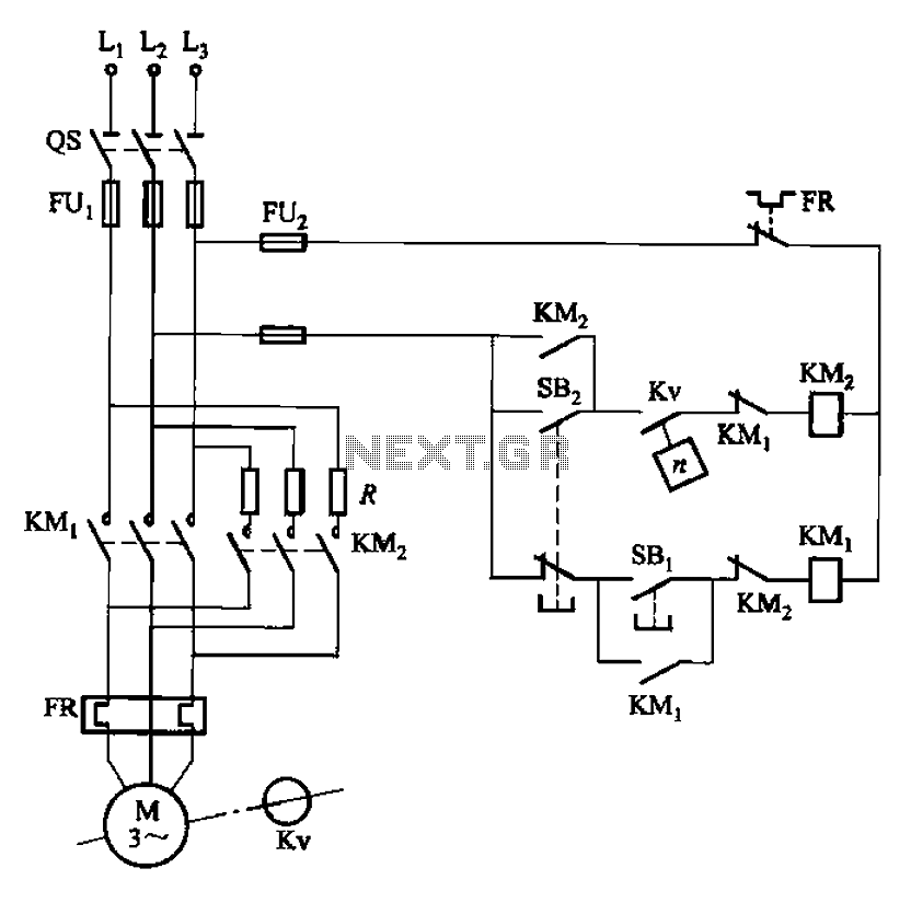
The circuit depicted in Figure 3-124 operates without an intermediate relay. Kv serves as the speed relay, activating when the electric motor speed exceeds 120 r/min while the contact is closed. If the speed drops below 100 r/min, the...
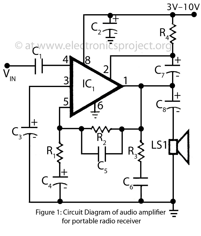
This is a simple audio amplifier circuit built around the BEL1895 1W audio amplifier integrated circuit (IC). This circuit serves as an alternative to more complex audio amplifier circuits designed for portable radio receivers. It does not require a...
Utilize this cell phone charger circuit along with a 1.5V battery when there is no main power available and charging your phone is necessary. This cell phone charger circuit is designed to provide a reliable charging solution using a 1.5V...