
Transformerless Power Supply

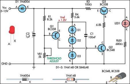
The transformerless power supply circuit is a compact and efficient solution for powering low-voltage devices directly from the AC mains supply without the need for a bulky transformer. This type of circuit typically employs a dropping capacitor to limit the current flowing into the load, allowing for a reduced voltage output suitable for various electronic applications.
In designing a transformerless power supply, the selection of the dropping capacitor is critical. The capacitor must be rated for the appropriate voltage and should have a capacitance value that ensures the output voltage remains within acceptable limits for the connected device. The value of the capacitor can be calculated based on the desired output voltage, load current, and the frequency of the AC supply.
Additionally, safety considerations must be taken into account when working with circuits connected directly to the mains. Proper isolation techniques and component ratings must be adhered to in order to prevent electrical shock hazards. The circuit may also include a rectifier, typically a diode bridge, to convert the AC output from the dropping capacitor into a DC voltage, followed by a smoothing capacitor to filter the rectified signal for a more stable output.
Furthermore, the design may incorporate a voltage regulator to maintain a consistent output voltage under varying load conditions. This is particularly important in applications where precise voltage levels are necessary for the proper operation of electronic components.
Overall, while transformerless power supply circuits can be advantageous for their simplicity and size, they require careful design and implementation to ensure functionality and safety.Transformerless Power Supply Circuit Diagram. Selection of the Dropping capacitor and the circuit design requires some technical knowledge and practical experience to get the desired voltage and current 🔗 External reference
Related Circuits
The distortion produced by a typical solid-state Class-B power amplifier consists of eight mechanisms, all of which may coexist and whose distortion products overlap to create a complex result. Methods for isolating each mechanism for study and minimizing its...
MC78L15ABPG positive voltage regulator, 100mA, TO-92 The MC78L15ABPG is a low-dropout (LDO) voltage regulator designed to provide a stable output voltage of 15V with a maximum output current of 100mA. This device is packaged in a TO-92 form factor, which...
The circuit is divided into two sections: the isolated external loop connected to the remote interface connector on the front of the power supply unit (PSU) and the non-isolated inner loop connected to the high-tension (AC line) supply. The...
This is a simple low supply rail detection circuit that is inexpensive and can be assembled in approximately 20 minutes. Its low power consumption makes it suitable for integration into battery-powered devices. Instead of utilizing an operational amplifier, the...
The LMD18200 is a 3A H-Bridge designed for motion control applications. The device is built using a multi-technology process that combines bipolar and CMOS control circuitry with DMOS power devices on the same monolithic structure. It is ideal for...
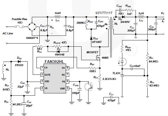
A simple 5-volt switching power supply electronic circuit project can be designed using the FAN302HL, a highly integrated PWM controller integrated circuit. This IC provides several features that enhance the performance of general flyback converters. The constant-current control of...