
Surveillance Transmitter Detector

This circuit design offers a straightforward approach to detecting the presence of surveillance devices within a given area. The use of a molded RF coil with a specific inductance value ensures that the circuit is sensitive to the desired frequency range, facilitating the detection of common surveillance signals. The high Q factor of the coil enhances the circuit's selectivity, allowing it to discriminate between the target signals and unwanted radio frequency interference.
The rectification process performed by the OA91 diode converts the alternating current (AC) signals received from the RF coil into a direct current (DC) voltage. This DC voltage is pivotal for biasing the Field Effect Transistor (FET), which acts as a signal amplifier. The choice of FET, whether MPF102 or 2N3819, provides flexibility in component selection based on availability and performance characteristics. The output from the FET is then measured by the analog meter, which visually indicates the presence of RF signals.
The adjustable preset resistor plays a crucial role in calibrating the circuit, allowing the user to set a baseline reading on the meter before scanning the environment. This feature enhances usability, ensuring that the circuit can be fine-tuned for optimal performance based on the specific conditions of the area being surveyed.
Overall, this circuit is a practical and efficient solution for individuals seeking to detect unauthorized surveillance devices, combining portability, simplicity, and effectiveness in its design.My site contains a few low power transmitters of one type or another, but until now no receiver. This circuit can be used to "sweep" an area or room and will indicate if a surveillance device is operative. The problem in making a suitable detector is to get its sensitivity just right; too much and it will respond to radio broadcasts, too little se
nsitivity and nothing will be heard. This project has few components, can be made on veroboard and powered from a 9 volt battery for portability. My prototype shown below, worked OK on a Eurobreadboard. Circuit operation is simple. The inductor is a moulded RF coil, value of 0. 389uH and is available from Maplin Electronics, order code UF68Y. (See my links page for component suppliers. ) The coil has a very high Q factor of about 170 and is untuned or broadband. With a test oscillator this circuit responded to frequencies from 70 MHz to 150 MHz, most of the FM bugs are designed to work in the commercial receiver range of 87 - 108 MHz.
The RF signal picked up the coil, and incidentally this unit will respond to AM or FM modulation or just a plain carrier wave, is rectified by the OA91 diode. This small DC voltage is enough to upset the bias of the FET, and give an indication on the meter. The FET may by MPF102 or 2N3819, the meter shown in the picture is again from Maplin Electronics, order code LB80B and has a 250 uA full scale deflection.
Meters with an FSD of 50 or 100 uA may be used for higher sensitivity. In use the preset is adjusted for a zero reading on the meter. The detector is then carried around a room, a small battery transmitter will deflect the meter from a few feet away. 🔗 External reference
Related Circuits
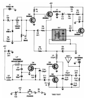
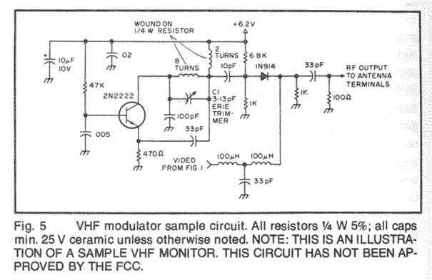
A low-power VHF TV transmitter is an essential tool for video enthusiasts, allowing the transmission of signals from a VCR to any television in a home or backyard setting. This device enables the convenience of watching movies by the...

This moisture detector with pump controller is built around the special purpose LM1830 IC. The LM1830 is designed to detect moisture by passing an AC current through a set of probes. An internal comparator compares the resistance of the...
In this fast-paced world, there is little time for inconveniences and a greater need for portability and adaptability. The idea for an Audio/Video transmitter stems from this need. There may have been times when you’ve wanted to hook up...

A simulation of a 27 MHz transmitter circuit is to be conducted using PSPICE. The circuit diagram is provided as Figure 1 in the following content. The 27 MHz transmitter circuit typically consists of several key components, including an oscillator,...

The output of this circuit will be activated when a mix of two tones or frequencies is detected at the input. The frequency, denoted as f, is determined by the values of resistor R1 and additional components. This circuit is...

A simple proximity detector circuit utilizing the NE567 integrated circuit (IC). The circuit activates an LED when an object approaches the sensor. The NE567 is a versatile phase-locked loop (PLL) device commonly used for applications such as proximity detection due...