
Moisture detector with pump controller
The circuit consists of several key components. The central component is the LM1830 fluid detection IC (U1), which operates by measuring the resistance between the stainless steel probes. When moisture is detected, the internal comparator activates the output to control the subsequent operation of the pump. The use of AC current prevents issues such as electroplating and corrosion, which are prevalent in DC systems.
The 555 timer (U2) is configured to create a delay, ensuring that the pump does not turn on and off rapidly in response to minor fluctuations in moisture levels. The timing duration can be adjusted using the linear taper potentiometer (R5), allowing for a customizable on-time ranging from approximately 5 seconds to 2 minutes. This feature is crucial for applications where continuous cycling of the pump would be undesirable.
The circuit also includes various resistors (R1, R2, R3, R4, R6) and capacitors (C1, C2, C3, C4, C5, C6, C7, C8) that set the operational parameters of the LM1830 and the 555 timer, ensuring stable performance. The power transistor (Q1) is utilized to drive the relay (K1), which controls the pump's operation based on the output from the LM1830. The relay should be selected based on the specifications of the pump being used. For a 12V pump, standard automotive relays are suitable, whereas for mains-operated pumps, relays with appropriate contact ratings must be employed.
Signal diodes (D1, D2) are included to protect the circuit from back EMF generated by the relay coil, while the rectifier diode (D3) ensures proper current flow in the circuit. The SPST switch (S1) enables manual control of the pump, providing an option for operation independent of moisture detection.
The stainless steel probes must be mounted in a non-conductive fixture, with materials such as Lexan, plexiglass, or plastic recommended for the housing. The probes should be positioned at the desired liquid level to ensure accurate moisture detection. Regular cleaning of the probes is advised to maintain reliable operation over time.
Overall, this moisture detector with pump controller is a sophisticated yet practical solution for applications requiring moisture monitoring and control, ensuring efficient operation while minimizing maintenance issues.This moisture detector with pump controller is built around the special purpose LM1830 IC. The LM1830 is designed to detect moisture by passing an AC current through a set of probes. An internal comparator compares the resistance of the probes to an internal reference. When the resistance between the probes is low (indicating the presence of water or other conductive liquid) then the IC triggers it's output. An AC signal avoids electroplating and corrosion problems that are common when DC is used. To provide an adjustable delay hysteresis to avoid cycling the pump, a timer based around the 555 is used a range of about 5 seconds to two minutes.
In this way the pump will stay active for a set amount of time even if the fluid level is below that of the probes. R1 1 470 Ohm 1/4 W Resistor R2, R4 1 10K 1/4 W Resistor R3 1 6.8K 1/4 W Resistor R5 1 1 Meg Linear Taper Pot R6 1 51K 1/4 W Resistor C1 1 470uF 35V Electrolytic Capacitor C2 1 0.001uF Ceramic Disc Capacitor C3 1 0.05 uF Ceramic Disc Capacitor C4 1 20uF 35V Electrolytic Capacitor C5 1 6.8uF 35V Electrolytic Capacitor C6, C8 2 0.01uF Ceramic Disc Capacitor C7 1 100uF 35V Electrolytic Capacitor U1 1 LM1830 Fluid Detection IC U2 1 555 Timer Q1 1 2N5305 NPN Power Transistor D1, D2 2 1N4148 Signal Diode D3 1 1N4002 Rectifier Diode K1 1 Relay With 12V Coil (See Notes) S1 1 SPST Switch PROBES 1 Stainless Steel Probes (See Notes) MISC 1 Case, Knob, Board, Wire, Sockets For U1 and U2 Notes The probes should be made of stainless steel and mounted in a non-conductive fixture. Stainless steel nails, bolts or welding rod will make ideal probes. Good non-conductive materials are Lexan, plexiglass or plastic. The probes are to be placed at the liquid level at which you wish the pump to turn on. K1 should be chosen according to the requirements of the pump. If you are running a 12V pump then common automotive relays will work fine. If you are running a mains powered pump then you will need to make sure the contacts are rated accordingly.
S1 provides a manual pump switch. R5 adjusts the on-time of the pump once moisture has been detected. It is adjustable from approximately 5 seconds to approximately 2 minutes. The probes should be cleaned periodically to assure reliable operation. 🔗 External reference
Related Circuits
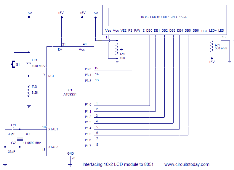
Interfacing a 16x2 alphanumeric LCD module with the AT89S51 microcontroller. The circuit diagram, theory, and program are included. JHD162 LCD module pinout and commands are provided. The integration of a 16x2 alphanumeric LCD module with the AT89S51 microcontroller involves several...
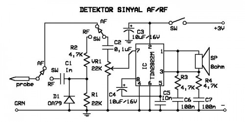
A signal detector circuit designed for detecting signals in both audio frequency (AF) and radio frequency (RF) ranges. This series is compact and straightforward to construct. The signal detector circuit operates by utilizing a combination of components such as diodes,...
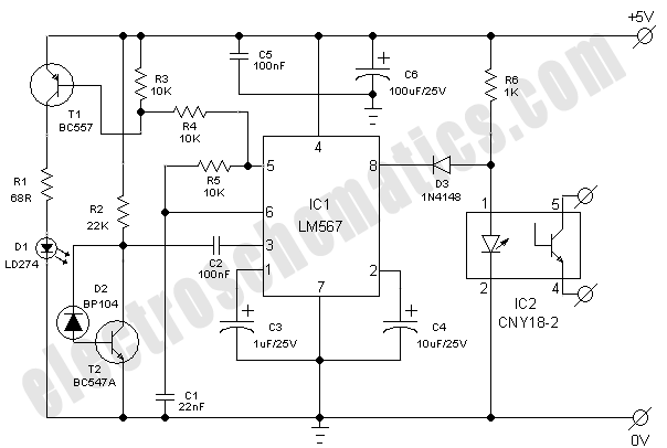
This simple and economical infrared model train detector circuit is designed specifically for hobbyists who want to incorporate a smart sensor to detect trains on their model railway track. The schematic diagram illustrates a straightforward configuration comprising an infrared...
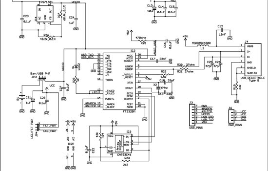
As found in SLAA458, the revised pulse oximeter application, an image of the USB schematic is attached, which is used to output collected data. There are a few questions regarding this schematic: 1) What do J3 and J6 correspond...
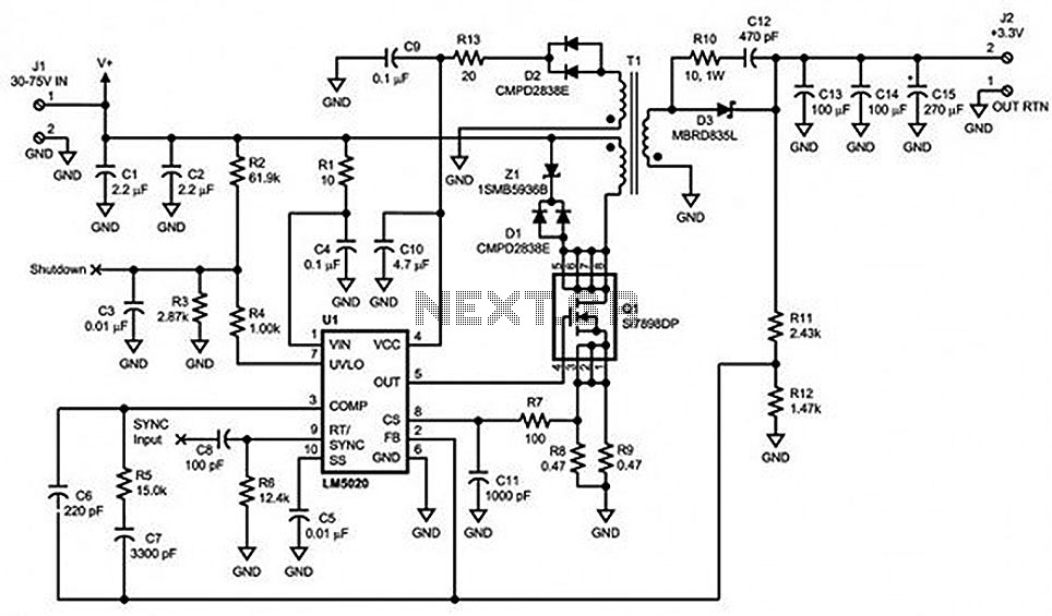
Locate sections such as the LM5020 connection diagram and pin descriptions, the functional block diagram of the device, the line under voltage lockout (UVLO) circuit, an internal high-gain error amplifier, a cycle-by-cycle overcurrent protection function, the setting of the...
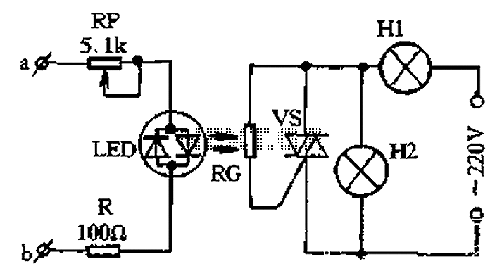
The circuit for a two-color music lantern controller is illustrated in Figure 1-44 below. Terminals a and b are located at both ends of the speaker, which receives audio signals. The audio signal is processed through a sensitivity adjustment...