
TV audio circuit diagram TDA1521
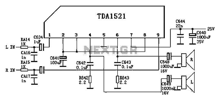
The TDA1521 integrated circuit is designed for audio amplification applications, particularly in configurations that utilize an output transformerless (OTL) approach. This amplifier is capable of delivering high-quality audio signals with low distortion, making it suitable for consumer audio equipment. The pinout configuration provides essential connections for both input and output signals, as well as power supply requirements.
Pin 1 serves as the reverse input for the left channel, allowing the circuit to receive audio signals. Pin 2 acts as the positive input for the left channel, where the audio signal is fed into the amplifier. Pin 3 is critical for reference voltage management, ensuring the amplifier operates within the correct voltage range depending on the connection type—either OCL (output capacitor-less) or OTL.
The output for the left channel is provided at Pin 4, which delivers the amplified signal to the speakers. Pin 5 connects to the ground, serving as the negative power supply input in OTL configurations, which is essential for circuit stability and performance.
For the right channel, Pin 6 provides the output signal, while Pin 7 connects to a 22V positive power supply, which is necessary for proper amplifier operation. Pins 8 and 9 serve similar functions as their left channel counterparts, with Pin 8 being the positive input for the right channel and Pin 9 acting as the reverse input.
Overall, the TDA1521 is a versatile audio amplifier that can be effectively utilized in various audio applications, delivering reliable performance and high-quality sound reproduction. Proper understanding of its pin configuration and voltage requirements is crucial for effective circuit design and implementation. Colour is often used as shown in audio circuit (TDA1521), the circuit is taken from Changhong C2191, the OTL two-channel connection. TDA1521 pin functions and reference voltage : Pin 1: 11V-- reverse input 1 (L-channel signal input) Pin 2: 11V-- positive input 1 3 feet: 11V-- Reference 1 (when the OCL connection to 0V, when the OTL connection is 1/2Vcc) 4 feet: 11V-- output 1 (L-channel signal output) 5 feet: 0V-- negative power supply input (connection to ground when OTL) 6 feet: 11V-- output 2 (R channel signal output) Pin 7: 22V-- positive power supply input 8 feet: 11V-- positive input 2 9-pin: 11V-- reverse input 2 (R-channel signal input)
Related Circuits
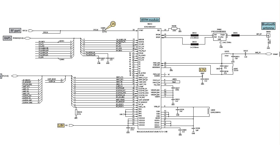
Bluetooth is an open wireless technology standard for exchanging data over short distances between fixed and mobile devices, utilizing short wavelength radio transmissions to create personal area networks (PANs) with high security. The Bluetooth baseband protocol combines circuit and...
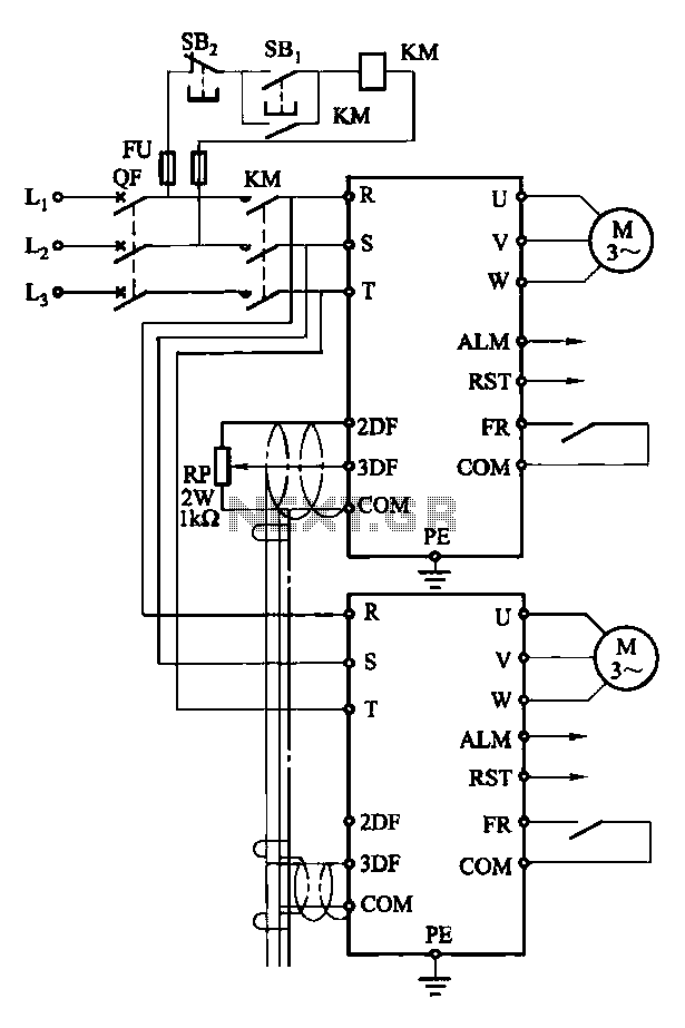
Each motor operates with an independent drive; however, only one frequency is utilized for a specific device. This setup employs a single RP potentiometer to control multiple motors in parallel. In this configuration, the circuit design allows for multiple motors to...
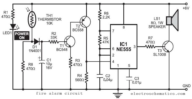
In this fire alarm circuit project, a thermistor functions as the heat sensor. When the temperature rises, its resistance decreases, and conversely, when the temperature falls, its resistance increases. Under normal conditions... In this fire alarm circuit, the thermistor is...

This circuit was designed by Lazar Pancic from Yugoslavia. A typical PC sound card includes a microphone input, speaker output, and occasionally line inputs and outputs. The microphone input is specifically tailored for dynamic microphones with an impedance range...
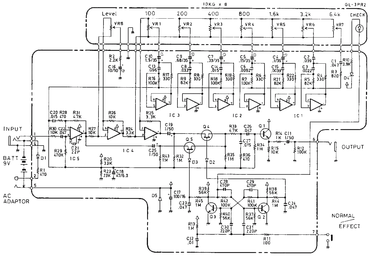
The Boss GE-7 Equalizer pedal modifies the harmonic content of an instrument across 7 distinct frequency bands, spanning from 100Hz to 6.4kHz, with a boost or cut of up to 15dB for each band. An additional Level control knob...

This circuit is designed to charge between one and twelve NiCd cells using a car battery. With switch S1 set to the normal position, it is capable of charging up to six cells. The circuit operates by utilizing a car...