
Switch mode power supply
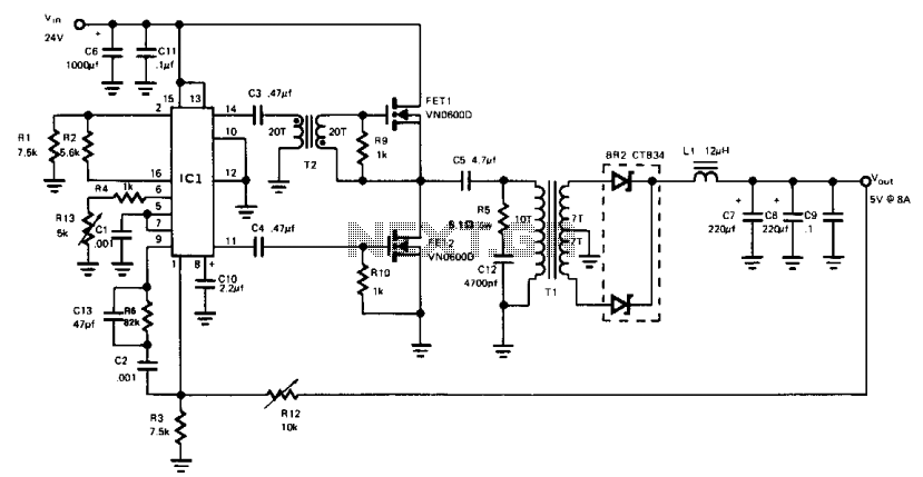
The described buck converter circuit is designed to efficiently step down a higher DC voltage to a lower DC voltage while providing a stable output current. The input voltage range of 24 to 32 V DC is suitable for various applications where such voltage levels are common, such as in industrial power supplies or battery-powered systems.
The operation of the circuit is based on the principle of pulse-width modulation (PWM), where the PWM125 controller regulates the duty cycle of the two power MOSFETs. By alternating the conduction of these MOSFETs, the circuit minimizes power losses and improves overall efficiency. The switching frequency of 150 kHz is a typical choice for such applications, balancing efficiency and component size.
The output from the MOSFETs is first transformed to a lower voltage level, which is crucial for ensuring that the final output meets the desired specifications of 5 V DC at a maximum current of 8 A. The transformation process may involve the use of an inductor and possibly a transformer, depending on the specific design of the circuit.
After voltage transformation, the signal is rectified to provide a smooth DC output. The rectification process typically employs diodes or synchronous rectification techniques to further enhance efficiency and minimize voltage drop.
The efficiency metrics indicate that the circuit performs adequately at lower input voltages, achieving 75% efficiency between 22 to 32 V. However, this efficiency can rise to approximately 90% when the input voltage is increased, showcasing the design's capability to adapt to varying input conditions while maintaining performance.
This buck-derived circuit is ideal for applications requiring efficient power conversion with specific output voltage and current requirements, making it suitable for a wide range of electronic devices and systems.This buck-derived circuit provides up to 8 A at 5 Vdc operating off 24 to 32 Vdc. The two power MOSFETs in the circuit conduct alternately for equal periods. Switching frequency is 150 kHz, set by the PWM125 controller. Output of the two MOSFETs is transformed to a low-voltage level, then rectified. Efficiency of the circuit is 75% when operated in a 22 to 32 V range. Efficiency approaches 90% with higher voltage inputs. 🔗 External reference
Related Circuits
Applying the filtered and rectified AC input to a high-input-voltage linear regulator is the simplest way to produce a low current level from an AC source. The process of converting an AC source to a low current level using a...
A new type of NiMH battery known as HeCell has recently been developed, which is claimed to allow higher discharge rates than the conventional ones (about 12 - 16C). The HeCell NiMH battery represents a significant advancement in battery...
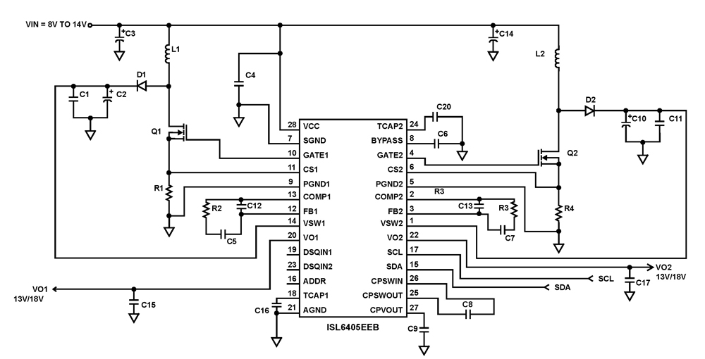
The ISL6405 is a highly integrated voltage regulator and interface integrated circuit (IC) designed to supply power and control signals from advanced satellite set-top box (STB) modules to the low noise blocks (LNBs) of two antenna ports. This device...
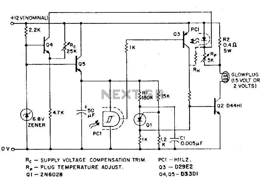
The circuit is designed for model airplanes, boats, and cars that utilize glow plugs for their miniature internal combustion engines (ranging from 0.1cc to 15cc). These engines are equipped with heavy batteries, high-tension coils, and capacitors necessary for classic...
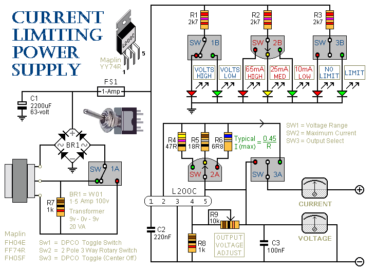
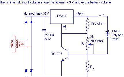
This is a 1-amp variable-voltage PSU. It adjusts from about 3v to 24v and has the added feature that you can limit the maximum output current. This is invaluable when, for example, you power-up a project for the first...
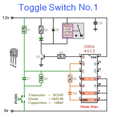
This circuit will activate and deactivate a relay with the press of a button. Any momentary push-to-make switch can be utilized. Pressing the button once will activate the relay, while pressing it a second time will deactivate the relay....