
toggle switch schematic with relay
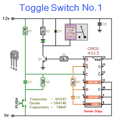
This circuit employs a simple toggle switch mechanism using a momentary push-button switch to control a relay. The relay acts as an electrically operated switch, allowing for the control of higher power devices with a low-power control signal. When the push-button is pressed, the circuit utilizes the flip-flop configuration of the CMOS 4013 to change the state of the relay, effectively toggling it between energized and de-energized states.
The choice of a relay is crucial; it must have a coil voltage that matches the power supply voltage selected for the circuit. The relay's contacts can be used to control various loads, such as lamps, motors, or other electrical devices, making this circuit versatile for different applications. The inclusion of an LED serves a dual purpose: it provides a visual cue for the user and can also be used for troubleshooting by indicating that the relay is powered.
In terms of component selection, the momentary push-button switch should be rated for the voltage and current it will handle. The single-pole relay can be selected based on the load requirements, ensuring that the relay's contact ratings exceed the load specifications. The CMOS 4013 IC is a dual D-type flip-flop, and since only one half is used, the other half can be reserved for future use, allowing for efficient utilization of components.
The circuit can be powered by a DC voltage source, and the design allows for a wide input voltage range, making it adaptable to various power supplies. The LED should be connected in series with a current-limiting resistor (R3) to prevent excessive current that could damage the LED. If the visual indication is not required, both the LED and resistor can be omitted without affecting the primary function of the relay toggling mechanism.
Overall, this circuit provides a straightforward solution for controlling devices with a simple push-button interface, with the added benefit of visual feedback through the LED.This circuit will energize and de-energize a relay at the push of a button. Any type of momentary action push-to-make switch can be used. Pushing the button once - will energize the relay. And pushing it a second time - will de-energize the relay I`ve drawn the circuit with a single pole relay. But you can use a multi-pole relay if it suits your a pplication. Only one half of the Cmos 4013 is used. So you could construct two independent toggle switches with a single IC. The circuit will work at anything from 5 to 15-volts. All you need do is select a relay with a coil voltage that suits your supply. The LED provides a visual indication that the relay is energized. In effect - it tells you whether the switch is on or off. It`s not necessary to the operation of the circuit. If you wish you may leave out R3 and the LED. 🔗 External reference
Related Circuits
Many microcontroller designs typically integrate various interfacing methods. A microcontroller (µC) system can be viewed as a system that reads from inputs. Microcontroller systems are versatile platforms that facilitate the integration of multiple interfacing methods to interact with various peripherals...
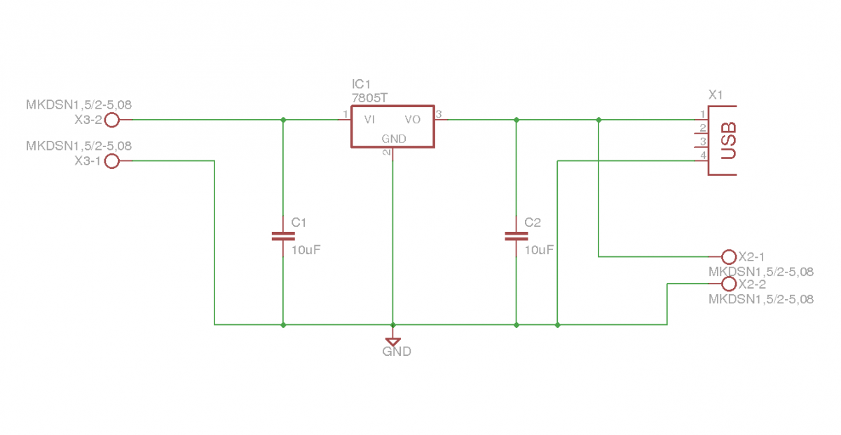
This document outlines the details of several circuits designed and built for a robot. The first circuit is a voltage regulator intended to supply power to a Raspberry Pi from a 7.2V battery. While the circuit is relatively simple,...
This is a single channel (on / off) universal switch that may be used with any Infra Red remote control using 36-38kHz. (This is a very common remote handset frequency). Any "button" of any remote control may be used...
The telephone ring generator shown below generates the needed high voltage from a simple switching mode power supply (SMPS) which employs a CMOS Schmitt Trigger square wave oscillator, 10 mH inductor, high voltage switching transistor (TIP47 or other high...
Connect the two sections of the variable capacitor (C3) in series to linearize the tuning somewhat. Use the connections on either end of C3 and do not use the middle lead. The gain is sufficient to drive an earphone....

An electronic rectification circuit that avoids the use of large, heavy, and expensive electrolytic capacitors by utilizing an active transistor in a gyrator configuration. To minimize excess ripple output on a power supply feeding a heavy load, a large...