
switch with relay schematic
The Light Switch with Relay circuit operates effectively by employing a Light Dependent Resistor (LDR) to sense ambient light levels. The LDR's resistance decreases as light intensity increases, allowing the circuit to respond dynamically to changes in illumination. The IC 741 serves as a critical component, functioning as a voltage comparator that compares the voltage across the LDR to a reference voltage set by the potentiometer P1. When the light level drops below a predetermined threshold, the output from the IC 741 changes state, triggering the transistor Q1. This transistor acts as a switch that energizes the relay, thereby turning on the connected lighting load.
The inclusion of the diode D1 is essential for protecting the circuit from voltage spikes caused by the relay coil's inductive load when it is de-energized. This protection is crucial in ensuring the longevity and reliability of the circuit components. The design flexibility allows for easy modification of the activation threshold by adjusting the potentiometer, making it suitable for various applications where automatic lighting control is desired.
Constructing the Light Switch with Relay circuit requires careful attention to the component specifications and proper assembly techniques to ensure functionality. The simplicity of the design, combined with its practical application, makes it an excellent project for both amateur and professional electronic engineers interested in automation and control systems. Overall, this circuit exemplifies a straightforward yet effective solution for enhancing energy efficiency and convenience in lighting control.Light Switch With Relay is a series of electronic switches that are controlled by a series of light received. Light Switch With Relay circuit can be used to control lighting automatically, so the lights can automatically turn on when the room light or the region began to decrease.
Limit of light used to activate the electronic switch in the circuit Light Relay Switch With This can be set via the potentiometer P1. P1 setting is basically a light reception sensitivity settings. Light Switch With Relay circuit uses the LDR as the light sensor and an IC 741 as a comparator and reference voltage sensor, relay driver transistor Q1 as as an electronic switch. A complete range of Light Switch With Relay is as follows. Circuit Light Relay Switch With diats a light switch that will be active when the sensor does not receive light, if you want to turn the tables (the active switch when the sensor receives light) it can be done by reversing the position between the LDR and R1.
Diodan D1 serves to avoid the effects of EMF or sparking of the relay coil. The circuit is simple and easy to make, I hope to provide ideas and descriptions in the manufacture of a controlled light switch. Hopefully useful. 🔗 External reference
Related Circuits
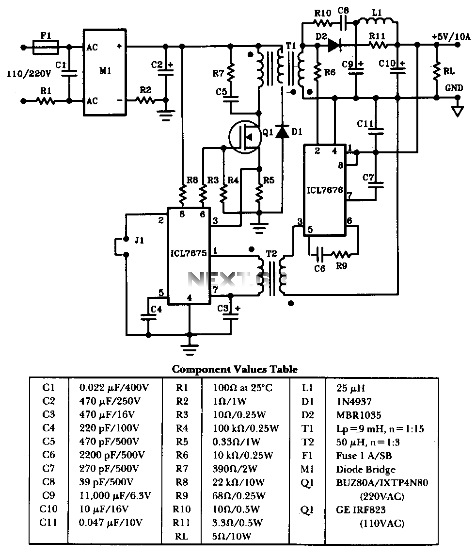
The schematic illustrates a 50W power supply providing a 5V, 10A output. It operates as a flyback converter in continuous mode. The circuit incorporates both primary and secondary side controllers, offering full protection against fault conditions such as overcurrent....
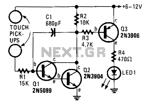
This circuit requires the bridging of two circuits to activate the electronic switch. It does not require a 60-Hz field to operate and can be powered by either battery or AC. The two pickup terminals can be made from...
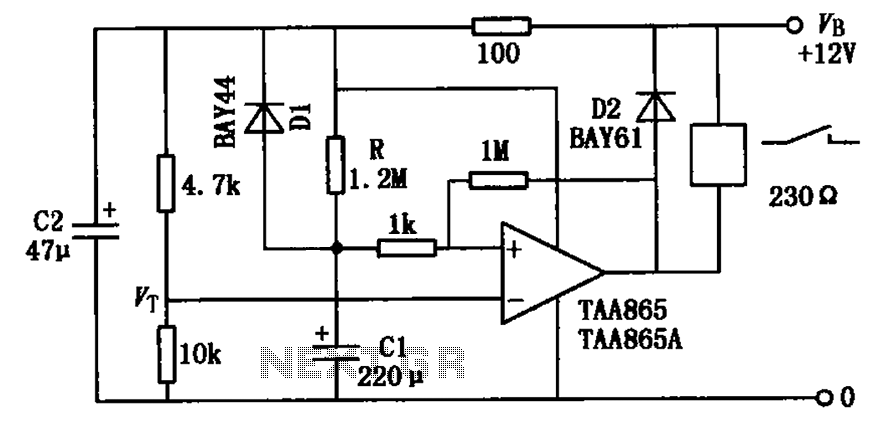
The circuit illustrated in the figure is a delayed release operational amplifier relay circuit. When the power switch is activated, a resistor of 4.7k is connected to the inverting input terminal of the operational amplifier. Additionally, a 10k resistor...
This circuit is basically a resistance sensing window switch, except that the resistor takes the form of an NTC thermistor and the circuit thus responds to temperature. TH1 must have a resistance in the range 500 ohm - 9...
Built around an LM380, this amplifier includes tone controls and electronic "soft switching". The soft switching circuitry ensures power is built up gradually eliminating the dc thump. The soft switching is enabled by a BD131 transistor wired as a...

The circuit utilizes six 12-volt lead-acid batteries to power the load. Three batteries are connected in series to generate 36 volts, while the other three are connected in parallel to maintain 12 volts. The total discharge current is 30...