
Temperature limit Relay
Part List
R1=4.7 K ohm TH1=NTC thermistor 500 ohm.....9 K ohm Q2=BC214L
R2=2.2 K ohm D1-2=1N4148 RL1=12V Relay >120 ohm
RV1-2-3=10 K ohm pot. D3=1N4001
This circuit operates as a temperature-sensitive switch utilizing an NTC (Negative Temperature Coefficient) thermistor, TH1, which decreases its resistance as the temperature increases. The resistance range of the thermistor, specified as 500 ohms to 9 k ohms, is critical for ensuring accurate temperature detection within the desired operating range.
The primary function of the circuit is to determine whether the temperature is above or below a predefined threshold. The variable resistor RV1 allows for calibration of the circuit to set a reference voltage at the junction of RV1 and TH1. This is essential for establishing the mean temperature point at which the circuit will trigger an output response.
The output stage of the circuit is driven by transistor Q2 (BC214L), which acts as a switch to control the relay RL1. The relay is rated for 12V and has a minimum coil resistance of 120 ohms, allowing it to be activated when the voltage at the collector of Q2 exceeds a certain level, indicating that the temperature has crossed the set threshold.
Resistors R1 and R2 are used to form a voltage divider, which helps to create the necessary biasing conditions for Q2. The diode components D1 and D2 (1N4148) serve as protection diodes to prevent back EMF from the relay coil from damaging the circuit when the relay is deactivated. D3 (1N4001) is likely used for additional protection or rectification purposes within the circuit.
The overall design emphasizes stability and reliability, ensuring that the circuit can effectively monitor temperature changes and activate the relay in response to those changes, making it suitable for applications such as temperature control systems, alarm triggers, or other automated systems requiring thermal regulation.This circuit, is basically a resistance ? sensing window switch, except that the ?resistor? takes the form of an NTC thermistor and the circuit thus responds to temperature. TH1 must have a resistance in the range 500ohm - 9Kohm. RV1 is used to set half ? supply volts on the RV1 ? TH1 junction at the ?mean? temperature. Part List R1=4.7Kohm TH1=NTC thermistor 500ohm.....9Kohm Q2=BC214L R2=2.2Kohm D1-2=1N4148 RL1=12V Relay >120ohm RV1-2-3=10Kohm pot. D3=1N4001 🔗 External reference
Related Circuits
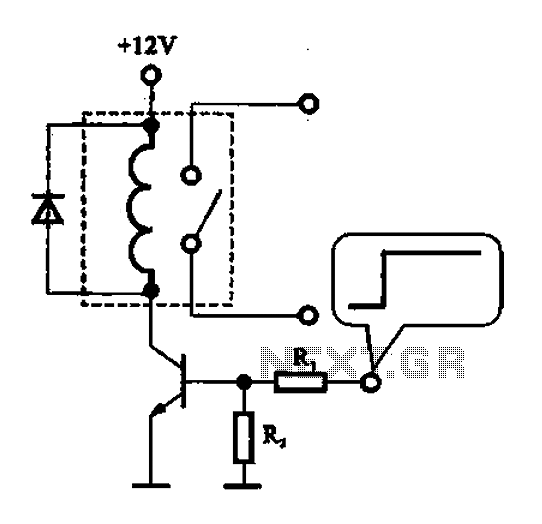
A relay control circuit is illustrated, which is commonly found in microwave switches. This circuit facilitates the operation of various components such as the power supply switch, electric fans, light bulbs, food turntables, and timers. The relay control signal...
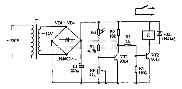
The circuit operates on 220V AC input, which is transformed to approximately 12V DC using a step-down transformer (T), a diode bridge rectifier (VDI-VD4), and a filter capacitor (C1). This setup is designed to power the entire circuit. The...
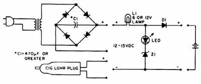
NiCd charger with current and voltage limiting power supply. This is a car NiCd battery charger circuit that can charge any Ni-Cd battery between 4.8 and 4.4 volts from a classic 12 volts car battery. The charging current can...
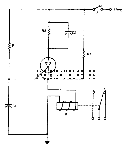
The relay operates for a specific duration, td, after power is applied, followed by an operating time, tc. The SCR activates when the voltage across capacitor Ci reaches a threshold voltage, VA. This action energizes the relay, which remains...
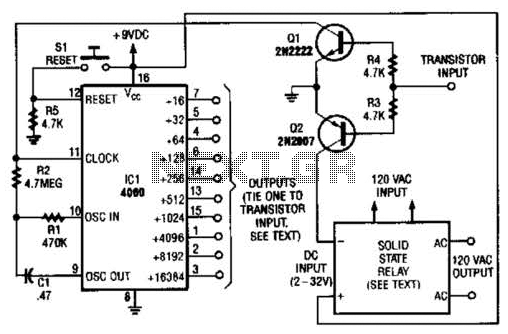
A long-duration timer can be easily constructed using a 4060 CMOS binary divider along with its integrated clock oscillator. The solid-state relay can be selected based on the specific application requirements and may be substituted with a mechanical relay...
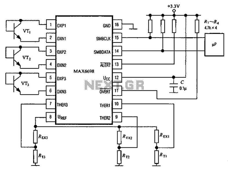
Channel 7 presents a circuit diagram of a smart temperature sensor using the MAX6698. This circuit includes three transistors (VT1, VT2, and VT3) and three thermistors (RT1, RT2, and RT3). An internal reference voltage source is provided via resistors...