
Switchable Output Crystal Oscillator

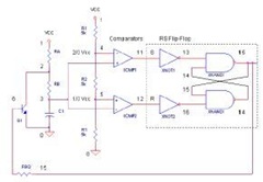
The oscillator circuit operates by utilizing a combination of logic control and feedback mechanisms to switch between different crystal frequencies. The core component, the LT1016 operational amplifier, is configured in a way that it maintains a stable output at half the supply voltage, which is critical for ensuring that the circuit can respond effectively to input changes. The resistors and the RC network play a pivotal role in establishing the gain and phase characteristics necessary for oscillation.
Upon the insertion of a crystal, the circuit enters a feedback loop that reinforces oscillation at the specific frequency of that crystal. This is facilitated by the removal of the short across D1, which allows the circuit to enter a state where positive feedback is sustained. The logic inputs A and B serve as control signals that selectively enable oscillation based on the desired frequency, providing flexibility in the oscillator's operation.
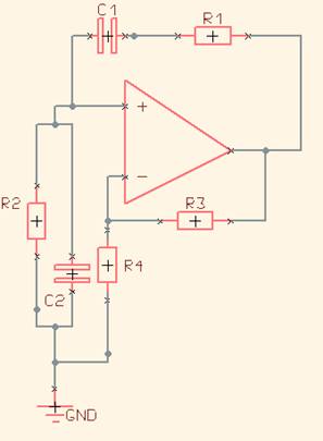
The design incorporates additional branches for multiple crystals, which can be selected through their corresponding diodes and resistors. This allows for rapid switching between frequencies, which is advantageous in applications requiring dynamic frequency adjustments. The stabilization time of approximately one millisecond for AT cut crystals is a consideration in timing applications, as it impacts the responsiveness of the circuit. The ability to operate at frequencies up to 16MHz demonstrates the circuit's capability for high-speed applications, although care must be taken to account for propagation delays that may occur in the comparator at these higher frequencies. Overall, this oscillator circuit exemplifies a sophisticated integration of analog and digital control elements to achieve versatile frequency generation.This oscillator circuit permits crystals to be electronically switched by logic commands. The circuit is best understood by initially ignoring all crystals. Furthermore, assume that all diodes are shorts and their associated 1kO resistors open. The two 1kO resistors at the non-inverting input of IC1 (LT1016) set the output to half the supply, ie, +2. 5V. The RC network from the output to pin 3 sets up phase-shifted feedback and the circuit looks like a wide-band unity gain follower at DC. When crystal X1 is inserted (remember, D1 is temporarily shorted) positive feedback occurs and oscillation commences at the crystal`s resonant frequency.
If D1 and its 1kO resistor are then considered to be part of the circuit, oscillation can only continue if logic input A is biased high. Similarly, the circuit can only operate at crystal X2`s frequency if logic input B is high. Additional crystal/diode/1kO resistor branches permit logic selection of the crystal frequency. For AT cut crystals about a millisecond is required for the circuit output to stabilise due to the high Q factors involved.
Crystal frequencies can be as high as 16MHz before propagation delays in the comparator prevent reliable operation. 🔗 External reference
Related Circuits
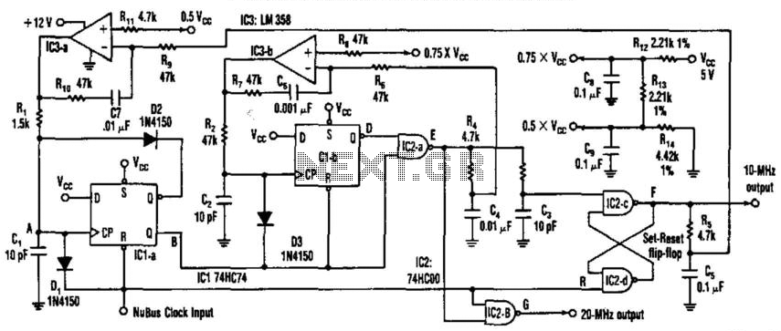
This circuit generates a 20-MHz clock signal that is phase locked to a 10-MHz clock found in the Apple MAC II. To create the 20-MHz output, the circuit generates a 25 ns negative-going pulse that is delayed by 50...

The circuit operates as a unijunction transistor relaxation oscillator. The base of the lower PNP transistor is biased at approximately half of the supply voltage. As the 100pF capacitor charges through the 1GΩ resistor, the base of the upper...
The 555 Timer IC operates in three modes: monostable, astable, and bistable/Schmitt trigger. This article will focus on its astable mode. The astable mode of the 555 Timer IC is characterized by its ability to generate a continuous square wave...
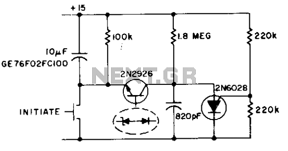
This circuit functions as both an oscillator and a timer. The 2N6028 transistor remains in an 'on' state due to the excessive holding current flowing through the 100 kΩ resistor. When the switch is briefly closed, the 10 µF...
This project is a piece of test equipment. It's a square wave oscillator with 6 selectable frequencies from 1Hz to 100kHz, incrementing in decade values. Its most useful application is as a Signal Injector for radios and TVs. A...
One of the simplest sine wave oscillators is the Wien Bridge Oscillator. Any circuit requires two conditions to oscillate. Tracing the path from the input, through the feedback network, and back to the input, there must be an overall...