
switches Using a momentary push button as a latching on-off toggle switch

The circuit described is a power control system utilizing a microcontroller and MOSFETs to manage the power supply through a push button mechanism. The TPS_EN line serves as the enable signal for the power regulator, which is initially held low by a pull-down resistor. This ensures that the regulator remains off until user interaction occurs.
Upon pressing switch S2, a ground signal is applied to the gate of MOSFET Q2, turning it on. This action allows the TPS_EN line to transition from low to high, thus enabling the power regulator. The regulator then powers the microcontroller, which is responsible for controlling the state of the latch outputs, LATCH_OP1 and LATCH_OP2. When these outputs are pulled low by the microcontroller, they activate Q2 and Q6.
The activation of Q6 creates a high signal at the terminals of switch S2, indicating that the system is ready for further user interaction. LATCH_OP1, by latching Q2, maintains a high signal on the enable line (VBATT), ensuring that the regulator remains powered as long as the button is pressed.
However, upon subsequent presses of the button, the circuit behavior changes. With Q6 already on, the application of VBATT to the gate of Q2 results in the deactivation of Q2, which in turn disables the power regulator. This sequence powers down the microcontroller, causing both latch outputs to revert to their high state. The intended operation of the circuit is disrupted at this stage.
The issue may stem from the interaction between the microcontroller's output states and the latch control mechanism. The manual adjustment of the latch lines to ground suggests that the microcontroller's control logic may not be correctly configured to maintain the desired states for LATCH_OP1 and LATCH_OP2 during operation. A thorough examination of the control logic and the timing of the signals is recommended to ensure proper functionality of the circuit as intended. Additionally, reviewing the connections and ensuring that there are no unintended shorts or floating signals may help resolve the operational discrepancies observed.An explanation of how the thing should work. The TPS_EN line is low at first. Since it is pulled down by a 10k pull down resistor(not shown in the schematic). When the user presses S2, the mosfet Q2 turns on because ground is applied to its gate. which enables the power regulator connected to the TPS_EN line. The regulator now starts up and starts powering the microcontroller. The microcontroller pulls the LATCH_OP1 and LATCH_OP2 low. The mosfet Q2 and Q6 now `turns on` due to this. Q6 is turned on and now causes the 1st and 2nd terminals of the push button s2 to go high. And the LATCH_OP1 causes the Q2 to latch thus enabling a constant high signal (VBATT)on the enable line. Now when the user presses the button Since Q6 was `on` the VBATT gets applied to gate of Q2 and turns off Q2.
The regulator turns off. turning off the microcontroller and the LATCH_OP2 and LATCH_OP1 return to VBATT. The circuit does not work as intended. I tried manually changing the latch lines to ground when turning on and it worked. But when i connect the lines to the microcontroller it does not work Please help me out! 🔗 External reference
Related Circuits
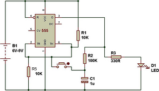
The circuit functions as a toggle switch, exhibiting two stable states: ON and OFF. When the circuit is in the ON state, it remains in that state until the switch is pressed again. The project is based on a...
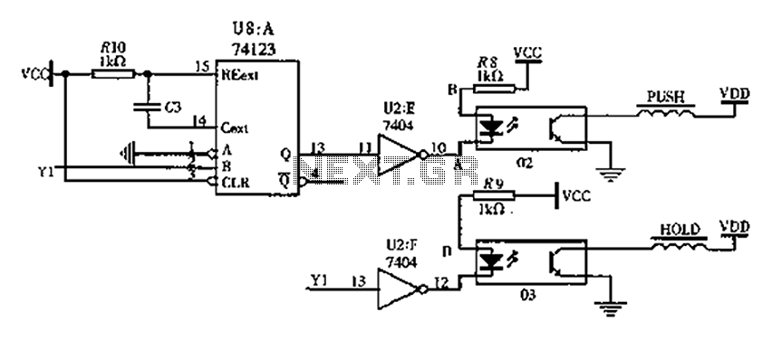
The FIG switching solenoid driver circuit utilizes the 74123 device chip (U8) and solid-state relays (02, 03). The switching electromagnet coil is referred to as the PUSH coil, while the HOL is maintained at a power supply voltage (VDD)...
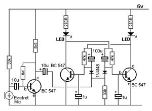
The Voice Electric (FC52) converts sound into electrical signals. The FC52 utilizes a high-gain glucose amplifier to amplify audio signals. When a clapping sound occurs, the sound signal is transformed into electrical signals and fed into the inverting input...
This project is useful if you wish to experiment with absolute phase, or are just interested in the possibilities of a polarity reversal circuit. In the case of absolute phase, many studies have shown that there can be an...
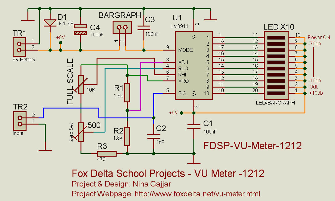
This simple VU meter can be utilized in a variety of projects. Since traditional electromagnetic VU meters are either no longer available or prohibitively expensive, this design employs the LM3914 integrated circuit and ten LEDs, allowing for versatile application...
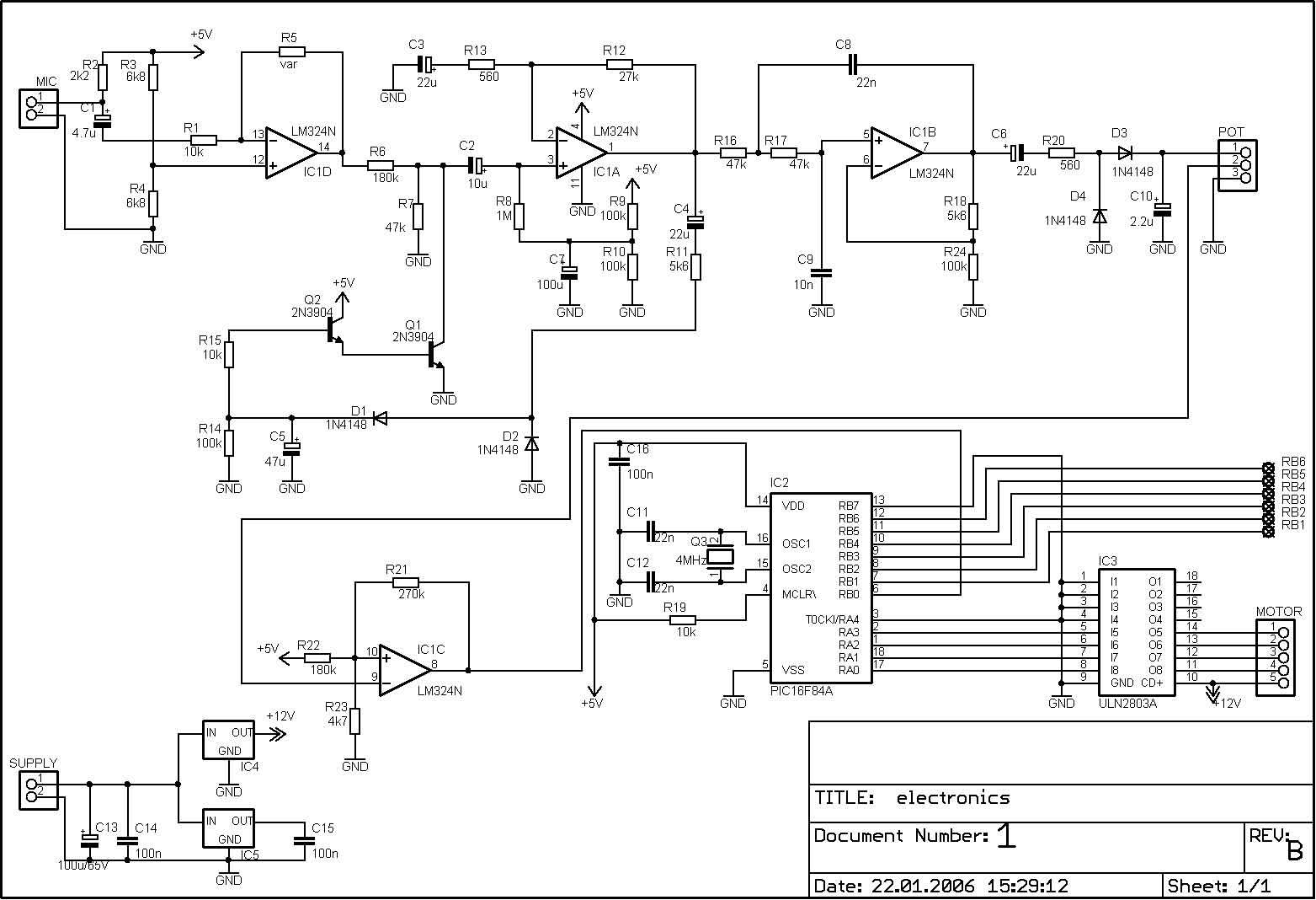
The PIC microcontroller is capable of controlling a motor after each beat, with the option to bypass certain beats using pushbuttons. The rotation speed and duration can also be adjusted within specified limits to prevent register overflow or underflow....