
Discolight effect with bass beat control using PIC
The described circuit utilizes a PIC microcontroller to manage motor operations based on audio input, specifically targeting beat detection. The system architecture includes an input stage that captures audio signals, typically from a microphone, which is then processed to identify beats. The microcontroller is programmed to interpret these beats as interrupts, allowing for responsive motor control.
To ensure reliable beat detection, the implementation of a debounce mechanism is crucial. The 200-millisecond delay following the first detected beat serves as a safeguard against false triggers caused by noise or reverberation in the environment. This timing can be adjusted based on the specific characteristics of the audio source, with the system calibrated to respond optimally to the expected signal amplitude.
The EEPROM functionality is essential for maintaining user-defined settings, such as motor speed and duration, across power cycles. This feature allows for a user-friendly experience, as the system can recall previous configurations without requiring reprogramming. The choice to use trimmers instead of potentiometers for sensitivity adjustments streamlines the design, as trimmers provide a more compact and stable solution for fine-tuning the gain of the microphone input.
The optical components, including the lens and parabola, are designed to focus light effectively, enhancing the visibility of the output beam. The placement of the barrier serves to optimize light transmission through the lens, ensuring that only the desired wavelengths are utilized in the final output. This meticulous attention to optical alignment is critical for applications that depend on precise light projection.
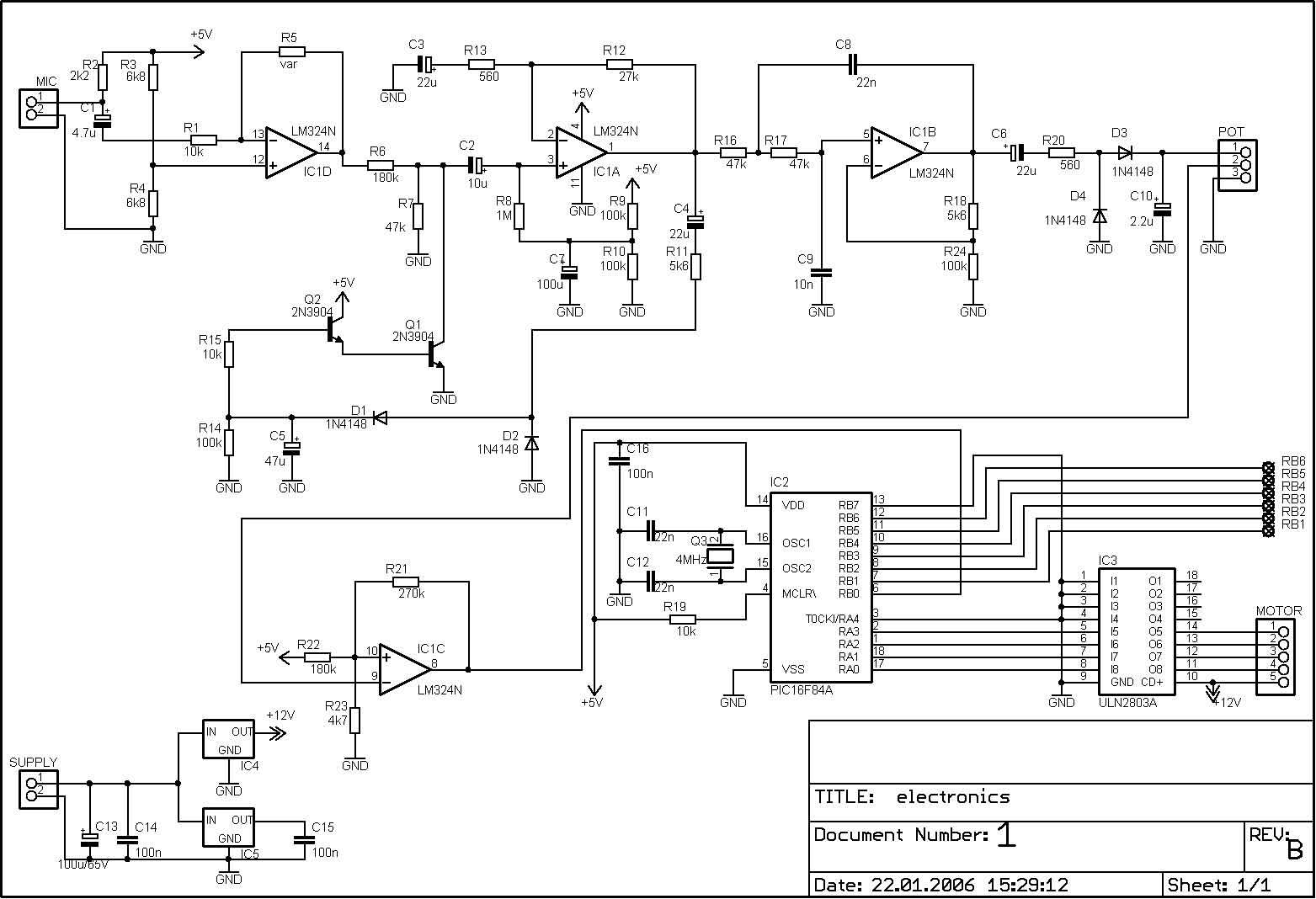
Overall, the integration of hardware and software in this project exemplifies a well-thought-out design that prioritizes functionality, reliability, and ease of use, making it suitable for various applications where motor control is synchronized with audio cues.The PIC can control the motor after every beat or its possible to bypass some beats. It can be done by pushbuttons. Rotation speed and rotation length can be adjusted too. Settings are limited between values to prevent possible register overflow-underflow. These values are saved in EEPROM so after shut-down the settings dont lost. A beat consist o f a series of vibrations (dont know the correct English word for that-sorry) so the PIC gets a few interrupts. To prevent multi-triggering theres a counter written into the code which disables reaction to beat for 200msecs after the first interrupt.
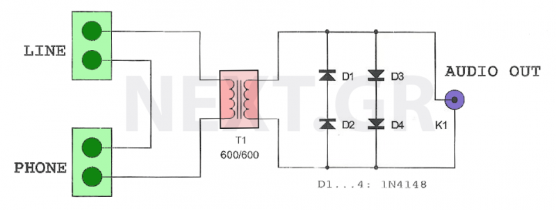
180msec delay is enough if you are using amplifiers output (or line out) as music source. I had to increase it to 200msec because i use microphone and the rooms echo influences operation. After you successfully built the whole hardware you need to adjust the trimmers very precisely. If you dont experiment a few times with adjusting them then its possible that the PIC will not recognise every beat because of the small amplification level. Or, it will do several things at only one beat. So you have to find the best adjustment. The original circuit which converts bass beat into pulses is from Dan Fraser (updated by Tomi Engdahl ).
I only replaced the line-out control with microphone and removed the 555 circuitry because of the software solution. The very-own in this project is the software for the PIC microcontroller. Because of the AGC circuit theres no need for potentionmeters for sensitivity adjust. I replaced them with trimmers. Now the microphone is on the control electronics because theres no need to place it outside the box and the possible noises from the surroundings are reduced.
You have to choose the distance between Lens-Lamp-Parabola to get sharp beams. Its all about optics. That little wall (hindrance) before the Lamp doesnt let the white light to passthrough the Lens. 🔗 External reference
Related Circuits
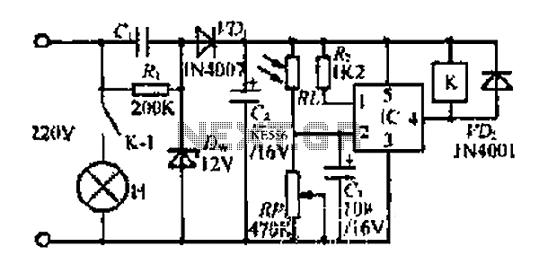
At dawn, light illuminates the photosensitive resistor RL, causing its resistance to decrease. This switch IC (2) exhibits a high electrical footprint. When light is present, the relay K does not activate. At night, in the absence of light,...
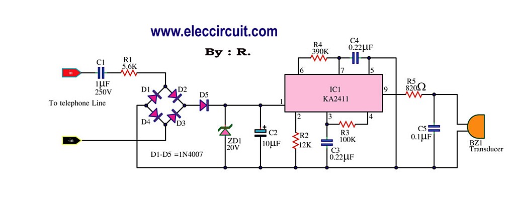
This circuit is designed to generate a loud ringing tone for an electricity bell in older telephones. It serves as a replacement for the original ringer, which may be lost, eliminating the need for a new phone. The circuit...
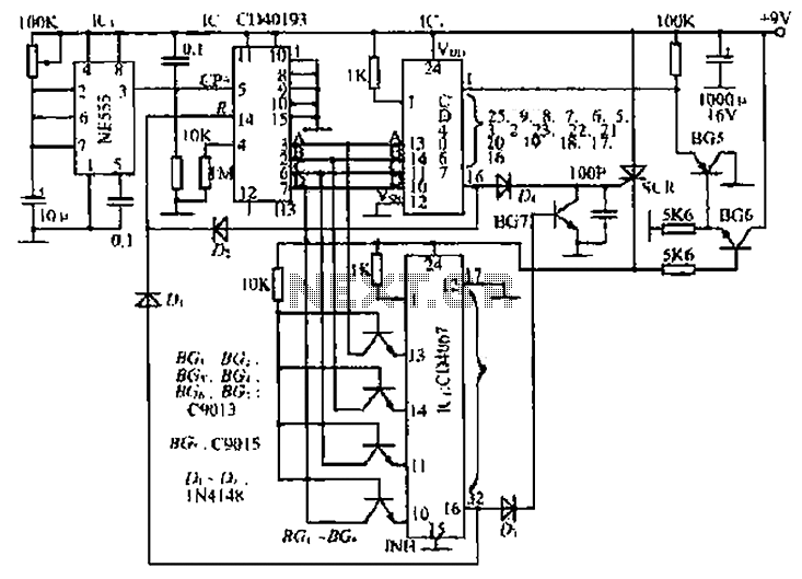
The circuit consists of an oscillator, a counter, and an Iseki circuit divided into three parts. The oscillator is based on the NE555 timer and several external RC components, generating a pulse signal for the counter. The instantaneous power...
This amplifier is designed for outdoor installation and is connected to an indoor power line box. It utilizes either 50-ohm or 75-ohm coaxial cables for the connection between indoor and outdoor units. The amplifier circuit board is depicted in...
This circuit is designed to record telephone conversations on a landline telephone. It requires a small circuit and a computer subscription. Recording conversations is useful for recalling important discussions. Previously, this was accomplished using a small tape recorder, where...

The PIC/Generation 1 electronics lack any form of current limiting. They depend on the resistance of the stepper motors to maintain the current below 2 Amps at 12 Volts. Unfortunately, the more commonly available stepper motors of the size...