
Polarity changer Switch

The primary benefit of the second circuit is that the op-amp remains in circuit all the time, and the switching is simplified. While this may not be important for some applications, it is useful nonetheless, and the circuit also shows the tremendous versatility of op-amps. The input resistors (R101, R201) are to ensure that the op-amp is biased even with no input connected. Also, note that the circuit (and the one in Figure 2) is DC coupled, so if there is any risk of feeding DC into the following power amplifier, then a capacitor should be used at the outputs of each channel. To ensure flat response down to low frequencies, a 10uF bipolar electrolytic may be used in series with each output.
The circuit described functions as a polarity reversal mechanism, utilizing an operational amplifier (op-amp) configuration to provide an inverting buffer. The primary components include a double pole switch, input resistors, and the op-amp itself. The switch allows the user to toggle between the original signal and the inverted signal, effectively shifting the phase by 180 degrees.
In terms of impedance considerations, the circuit is designed to maintain a low source impedance to minimize errors in signal levels between the normal and inverted outputs. The input impedance with the switch open is significantly high, while closing the switch reduces it to 11kΩ, which is manageable but should be monitored to avoid signal degradation. The choice of resistor values is critical; while higher values may reduce noise, they can also introduce stray capacitance issues, necessitating careful selection based on the application requirements.
The op-amp remains engaged in the circuit at all times, which simplifies the switching mechanism and enhances the versatility of the design. The input resistors are crucial for proper biasing of the op-amp, ensuring that it operates correctly even in the absence of an input signal. The circuit is also DC coupled, which necessitates the use of coupling capacitors at the outputs to prevent DC offset from affecting downstream components, particularly power amplifiers.
For applications requiring a flat frequency response down to low frequencies, the inclusion of a 10uF bipolar electrolytic capacitor in series with each output is recommended. This ensures that the circuit can handle a wide range of audio frequencies without introducing phase distortion or signal loss. Overall, the described polarity reversal circuit offers a robust solution for audio applications where phase experimentation is desired.This project is useful if you wish to experiment with absolute phase, or are just interested in the possibilities of a polarity reversal circuit. In the case of absolute phase, many studies have shown that there can be an audible difference between polarities, but be aware that there is no way to really know for certain what the original phase was.
Typical microphone methods mean that in some cases the polarity may be reversed compared to the way you may hear the same sound live. As a result, there is not necessarily a 'correct' polarity, since there are so many different ways that a signal may be processed before you hear it.
The more conventional method is shown in Figure 1, and is simply an inverting buffer with a switch. Simple, and does exactly what is needed, but as noted above requires a double pole switch and 3 wires for each channel. While there is no requirement to have an especially low source impedance, it is highly recommended that it be as close as possible to that used for the inverter (typically 100 Ohms).
By selecting the normal output or that from the inverter, the output polarity is inverted (or shifted by 180° if you prefer). The additional loading on the normal output is negligible, but it must be low impedance to prevent the normal and inverted signals from having different output impedance, and therefore possibly different levels.
This circuit has similar constraints to the previous version - source impedance should be low, and in this circuit the impedance changes when the switch is opened or closed. With the values shown, Zin will be very high (typically >1M?) with the switch open, and 11k with it closed.
This can be increased if desired by increasing the value of all resistors. A maximum of 100k is suggested to keep noise to the minimum, and to ensure that stray capacitance does not cause a problem (see construction notes below for more detail). Source impedance should be no more than around 220? if you use 22k resistors, or about 1k if you use 100k resistors. This gives an error of a little under 0.15dB. For less error between normal and inverted, use a lower source impedance. The primary benefit of the second circuit is that the opamp remains in circuit all the time, and the switching is simplified.
While this may not be important for some applications, it is useful nonetheless, and the circuit also shows the tremendous versatility of opamps. The input resistors (R101, R201) are to ensure that the opamp is biased even with no input connected.
Also, note that the circuit (and the one in Figure 2) is DC coupled, so if there is any risk of feeding DC into the following power amplifier, then a capacitor should be used at the outputs of each channel. To ensure flat response down to low frequencies, a 10uF bipolar electrolytic may be used in series with each output.
🔗 External reference
Related Circuits
A two-line intercom with a telephone changeover switch. This circuit can connect two telephones in parallel and function as a 2-line intercom. Typically, a single telephone is connected to a. The two-line intercom circuit is designed to facilitate communication between...

Four 4.8 Volt 2000mA Nickel Cadmium batteries require a safe method for initial charging using a lab power supply, as a specific NiCad charger is not available. Assistance is sought for circuit drawings of a simple NiCad charger. The...
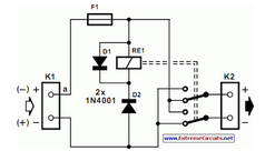
There are systems in which it is essential for the supply voltage of a motor to consistently maintain the correct polarity. It is certainly feasible to utilize a... In motor control systems, ensuring that the supply voltage maintains the correct...
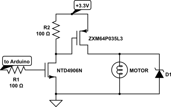
Charge a simple servo that only has + and - pins. Typically, the - pin is connected to ground, while the + pin is connected to a digital output from an Arduino. This setup works, but the servo operates...
A video switcher circuit is required to display multiple sources on a single monitor. The circuit schematic below features the MAX454, which serves as the core component of this video switcher. The MAX454 is a video multiplexer-amplifier manufactured by...
An AC triggered switch for low frequency signals. This is a basic ac voltage operated switch made from discrete components. Both Q1 and Q2 work as common emitter amplifiers, but the biasing of Q1 is arranged by R3 and...