
switching between parts circuit pulse input

The circuit design begins with a 9V DC power source that feeds into a 555 timer configured in astable mode, generating a square wave output. This square wave is then directed to a Half-Wave Series Multiplier, also known as a Villard Cascade, which increases the voltage to the desired range of 30-40V. The output of this multiplier can be utilized for various applications, including muscle stimulation.
To achieve the desired output voltage levels with minimal complexity, a boost converter is recommended. The boost converter will step up the voltage from the 9V source to the required levels while allowing for control via a microcontroller. The microcontroller can provide a 5V control signal to a MOSFET switch, which will toggle between the two output voltages. The use of a MOSFET is advantageous due to its low on-resistance and high switching speed, which is critical for efficient operation.
The NCP3063 integrated circuit is suitable for this application due to its capability to handle input voltages up to 40V and its built-in switching functionality. The circuit should include an inductor and a Schottky diode to facilitate the boost conversion process. The selection of the inductor and diode must be based on the desired output current and voltage specifications, ensuring that the components can handle the operational requirements without overheating or failing.
The circuit's design should also consider the need for pulse width modulation (PWM) to control the output voltage effectively. By adjusting the duty cycle of the PWM signal, the output voltage can be regulated, allowing for precise control over the stimulation provided to the electrodes.
In summary, the circuit will be powered by a 9V battery, utilize a 555 timer for square wave generation, and employ a boost converter with a MOSFET switch to achieve the desired high voltage output while maintaining a low current draw suitable for muscle stimulation applications. The entire setup will be cost-effective and straightforward, allowing for easy assembly and operation.This is a 9V DC power source, to a 555 timer to get a square wave. Then fed through a Half-Wave Series Multiplier (Villard Cascade) to get a high voltage DC output. Ideally I want to be able to send a single pulse at 5V pulse from a micro-controller to the switch to change the resulting output of the system between those two points. I think that I should include basically what I am trying to accomplish with this circuit as it seems that I may have chosen possibly the wrong path to pursue. First off, I wish to be able to power the circuit off of a battery source, hence the 9VDC. What I wish to accomplish is to get a about 30-40V square wave output. I was going to add another 555 timer at the end of the diagram that I originally posted to get the square wave.
So I guess it`s kind of a circuitous route to take, DC->AC->DC->AC, lol. Firstly, it is easier to have a level from a microcontroller so that high = one voltage and low = the other voltage. I don`t know if that is what you intended. Secondly, you could lower your component count a lot by using a boost converter. You can easily get a microcontroller to change the output voltage of a boost converter. I assume that you want two possible fixed output voltages, and a boost converter would be good for that.
First off, I wish to be able to power the circuit off of a battery source, hence the 9VDC. What I wish to accomplish is to get a about 30-40V square wave output. I was going to add another 555 timer at the end of the diagram that I originally posted to get the square wave. So I guess it`s kind of a circuitous route to take, DC->AC->DC->AC, lol. Thanks for all your help. Im going to go with a boost converter instead with a MOSFET as the switch. All I have to do now is specify which diode and inductor to use. Any thought I am trying to limit the current draw. This circuit will be part of a larger device, but essentially it will be to output a square wave to muscle stimulating electrodes.
Hence the desired low current. I would like to limit it to under 100mA as to not cause skin irritation. The switch toggles Q14 and Q15 every time the switch is depressed. The duration of switch activation has no influence on the function. However to toggle again the switch must be released for a short time. (to have the input return to ground) The first half of the IC produces a needle shaped pulse to trigger the second half. Is it possible to use a MOSFET in the original circuit design I have above Since a transistor only passes current and not voltage, correct Also, how does a transistor negate the voltage potential The NCP3063 is an enhanced version of the old MC34063 with a max switching freq of 150kHz using the internal switch and up to 250kHz with external switch.
For your low power you don`t need an external switch. You can download an excel spread sheet that will calculate all external components. In your case all you will need is an inductor a Schottky diode and a few other passives. Forgot to add you should be able to build this for about a buck. Just buy everything you need from one distributor to minimize shipping cost, and if your not in any particular hurry just use snail mail for delivery rather then a courier like UPS etc. Thanks for the link. It`s helped me understand pulse width modulation more. I guess with this chip I won`t have to go through setting up a mosfet inductor and a diode now. I just wanted to make sure I am reading the specsheet correctly. It states that the input voltage is operation to 40V, but I cannot find the operational voltage. However it says that Vcc is 0 to 40V. So I am kind of confused there. But an input of 18V will be able to power it (2x 9V batteries), or 4. 8V (4x AA batteries), correct. In order to run the circuit, I will just have to set it up according to figure 19 in the specsheet correct And depending on the pwm of the on off, I will be able to output basically any voltage such as
🔗 External reference
Related Circuits
The following circuit is a basic 555 square wave oscillator. Features include a 1 kHz tone, simple circuitry, a current limit of 200 mA, reduced inductive voltage, and a supply voltage range of 4.5 to 9 volts. Components used...
This project involves a simple circuit designed to mix two or more audio channels into a single channel, such as converting stereo audio into mono. The circuit is capable of accommodating multiple input channels while maintaining low power consumption....
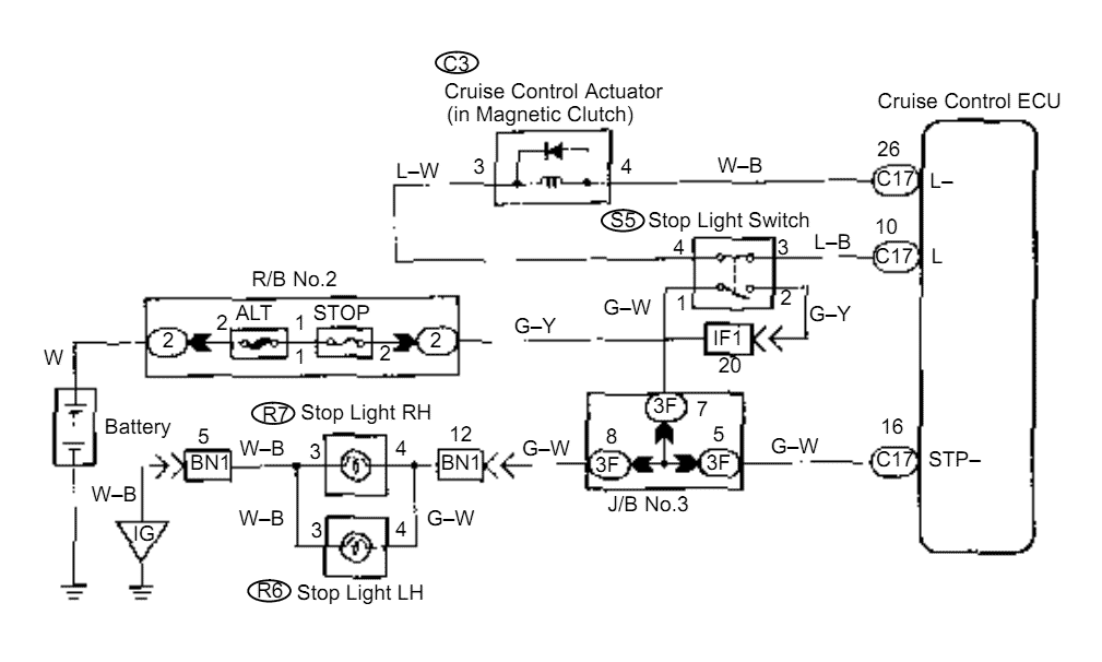
When the brake pedal is depressed, battery positive voltage normally applies through the STOP fuse and stop light switch to terminal STP of the ECU, and the ECU turns the cruise control off. A failsafe function is provided so...
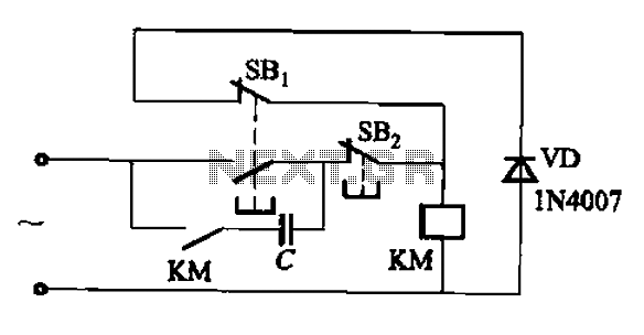
An AC contactor switch, when used with DC or pulse DC excitation, can minimize short circuit and core power consumption. This results in a significant reduction in the power consumption of the electromagnet, which can eliminate noise and reduce...
In pulse position modulation, the amplitude and width of the pulses are kept constant, while the position of each pulse with reference to the position of the reference pulse is changed according to the instantaneous sampled value of the...

This circuit diagram of a digital clock utilizes six common anode seven-segment displays to indicate the time. It does not require microcontrollers or PICs for operation. The circuit operates using the MM5314 integrated circuit, functioning at either 50 Hz...