
Simple pulse position modulation circuit

Pulse Position Modulation (PPM) is a modulation technique where the information is encoded in the timing of the pulses rather than their amplitude or width. In PPM, each pulse maintains a constant amplitude and duration, which are critical for ensuring signal integrity and reducing distortion during transmission. The key characteristic of PPM is that the position of each pulse is varied in relation to a reference pulse, which serves as a timing marker.
This modulation scheme operates by sampling the modulating signal at discrete intervals. The sampled values dictate the timing of the output pulses, effectively shifting the pulse position forward or backward in time based on the amplitude of the sampled signal. For instance, a higher amplitude sampled value would correspond to a pulse being transmitted earlier in the time frame, while a lower amplitude would result in a later pulse position.
PPM is particularly advantageous in applications where bandwidth efficiency is critical, as it can achieve high data rates without requiring a significant increase in bandwidth. Furthermore, because the amplitude of the pulses remains constant, PPM can be more resilient to noise and interference compared to amplitude modulation techniques.
In practical implementations, PPM can be utilized in various communication systems, including optical communication, radio frequency transmission, and digital data transmission. The design of a PPM system typically involves components such as sample-and-hold circuits, pulse generators, and demodulators, which work together to encode and decode the information accurately. The careful design of these components is essential to ensure that the timing of the pulses is precise, thereby maintaining the integrity of the transmitted information.In pulse position modulation, the amplitude and width of the pulses are kept constant, while the position of each pulse with reference to position of reference pulse, is changed according to the instantaneous sampled value of the modulating signal 🔗 External reference
Related Circuits
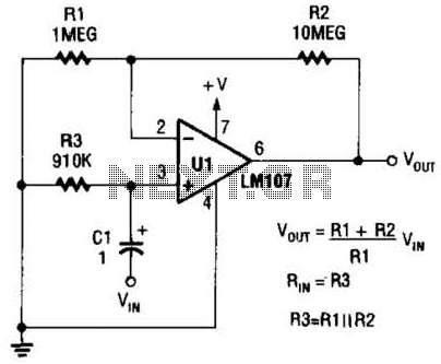
A general-purpose noninverting AC amplifier for audio and other low-frequency applications is presented. Design equations are included in the figure. Almost any general-purpose operational amplifier can be utilized for U1. The circuit configuration features a noninverting amplifier topology, which is widely...
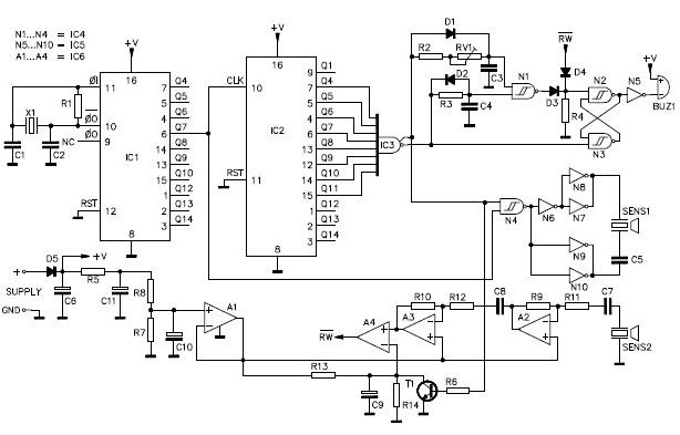
A simple ultrasonic parking sonar electronic project can be designed using this schematic circuit. This ultrasonic parking sonar project features an adjustable detection range from 5 cm to 1.5 meters and a detection angle of 5 degrees. The circuit...
This page outlines the development of electronics for displaying a monochrome video image on an electrostatic oscilloscope tube. This work complements the Electron Optics section in the Experiments category. The primary objective is to showcase a moving video image...
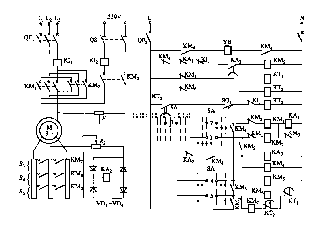
Figure 3173 illustrates a control circuit for a wound rotor induction motor that enables mechanical braking, dynamic braking, and reverse braking functions. The circuit includes various components such as relays, contactors, and time relays to manage the motor's speed...
Figure 2-32 (a) illustrates the time control diagram for a motor operated by switch S1. When S1 is set to position 1, the power driver circuit supplies current to the motor, enabling it to run. When S1 is switched...
This circuit is designed to protect a power supply or battery. The electric current will be interrupted by a relay when a short circuit occurs. Relays must be selected with a voltage rating equal to the input voltage. It...