
Switching inverter for 12v systems
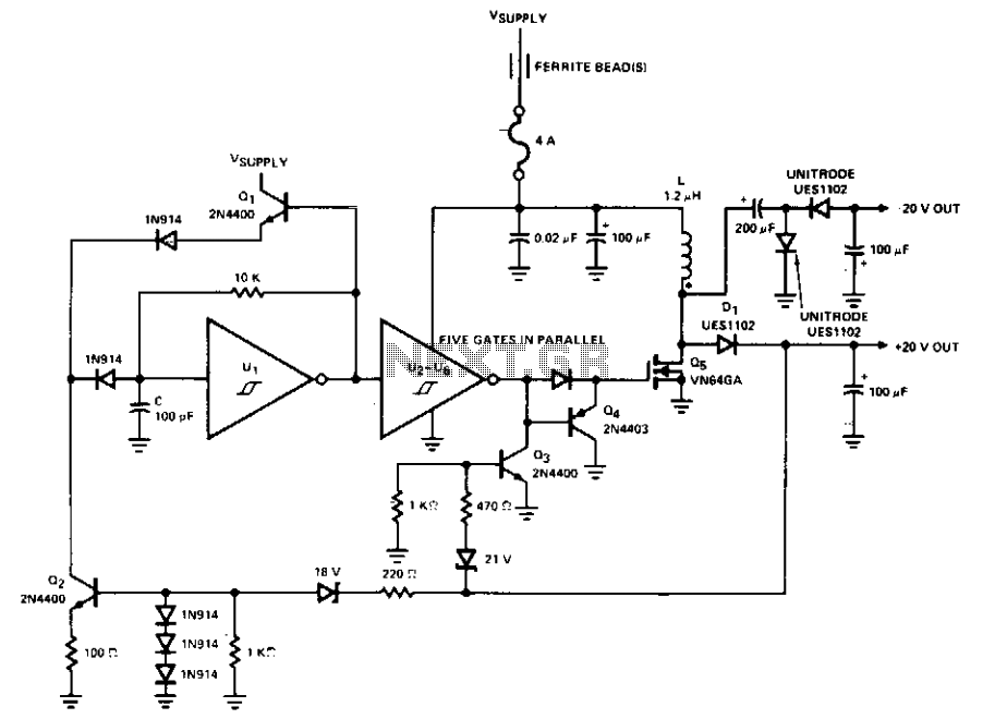
The PWM control circuit is a critical component in managing the operation of the DMOS power switch within a flyback converter. The circuit utilizes a pulse-width modulation technique to regulate the power delivered to the load. The width of the PWM output pulse is directly influenced by the input control voltage, allowing for precise control over the energy transferred to the output.
The external clock signal is essential for defining the frequency of the PWM operation, which in turn dictates how often the DMOS switch is turned on and off. The frequency selection is crucial for optimizing the performance of the flyback converter, as it affects both the efficiency and the response time of the circuit.
The inclusion of an error amplifier is vital for maintaining the desired output voltage level. This component continuously monitors the output voltage and compares it to a predetermined reference voltage. Any discrepancy between the two values generates an error signal, which is then fed back to the PWM controller. This feedback mechanism ensures that the output voltage remains stable even as the load conditions change, effectively compensating for variations in load demand.
The reference voltage serves as a benchmark for the error amplifier, determining the target output voltage for the circuit. By adjusting the control voltage based on the feedback from the error amplifier, the circuit can dynamically respond to changes in load, maintaining performance and preventing issues such as voltage spikes or drops.
In summary, this PWM control circuit exemplifies a robust design that integrates control, feedback, and stability mechanisms to efficiently manage the operation of a DMOS power switch in a flyback converter application. The synergy between the PWM output, error amplifier, and reference voltage forms a comprehensive control system akin to that found in servo mechanisms, ensuring reliable and effective power management.This PWM control circuit provides the control pulse to the DMOS Power Switch in the flyback circuit. The output of the PWM is a pulse whose width is proportional to the input control voltage and whose repetition rate is determined by an external clock signal. To provide the control input to the PWM and to prevent the output voltage from soaring or sagging as the load changes the error amplifier and reference voltage complete the design.
They act as the feedback loop in this control circuit much like that of a servo control system. 🔗 External reference
Related Circuits
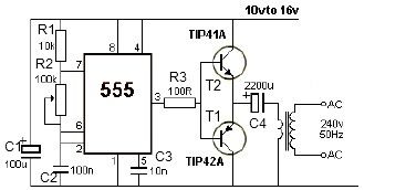
This 12V power inverter circuit can be utilized to power small devices that require 240 volts. It is particularly advantageous for operating 240-volt appliances using a 12-volt car battery. Unlike typical feedback oscillator inverters, this design employs a 555...
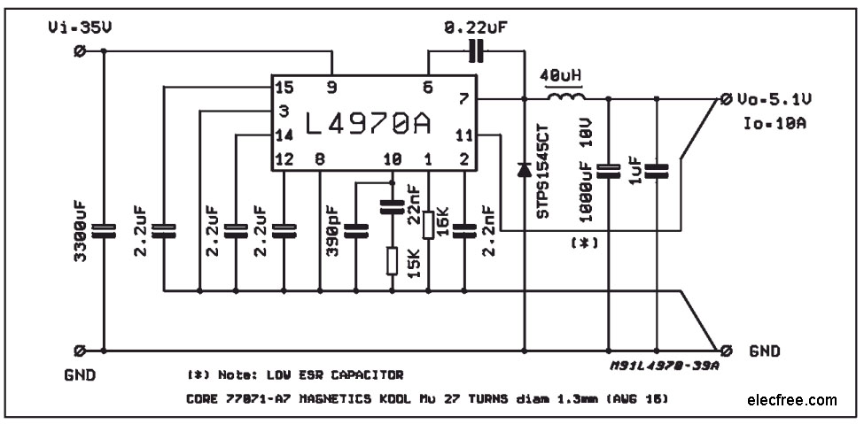
A compact and easy-to-build 5V 10A power supply circuit is sought. This circuit utilizes the L4970A IC as a 10A switching regulator. It is designed to be straightforward, serving as an example of an integrated ready-made circuit. An important...
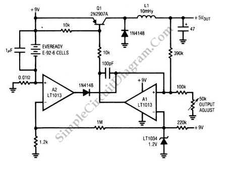
A circuit of a low-power switching regulator is illustrated in the schematic diagram below. This circuit can provide an output voltage of 5V from a 9V source. The efficiency... The low-power switching regulator circuit is designed to convert a higher...
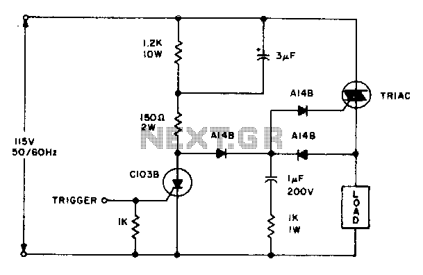
The triac will be activated at the beginning of the positive half cycle due to the current flowing through the 3 µF capacitor, provided that the C103 SCR is in the off state. The load voltage subsequently charges the...
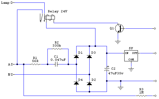
The objective is to add a security sensor light near the main entrance that operates on 12 volts. While 12-volt PIR sensors are available, they tend to be costly, often exceeding $50 each and are specifically designed for security...
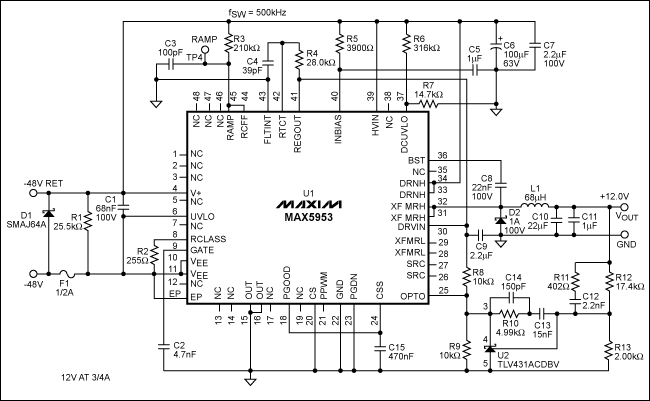
The MAX5953A offers a straightforward, cost-effective, and comprehensive non-isolated power integrated circuit (IC) solution for Powered Devices (PD) in Power-over-Ethernet (PoE) systems. The MAX5953A is designed to facilitate the implementation of Power-over-Ethernet applications by providing an efficient means of...