
SWR Meter

The described SWR meter is a sophisticated device that facilitates direct measurement of standing wave ratio (SWR) without manual adjustments, making it user-friendly and efficient. The core of the system is the utilization of two AD8307 RSSI chips, which are integral in converting RF signals into DC voltages. These chips operate on the principle of logarithmic amplification, allowing for a wide dynamic range and enabling accurate readings across varying power levels.
The operational amplifier's role in the circuit is to perform a differential measurement of the forward and reflected voltages, which directly correlates to the SWR value. This method enhances the accuracy and reliability of the readings, as the output is less susceptible to variations in the input power levels. The incorporation of a directional coupler, specifically the "Stockton" design, is critical as it ensures that the RF samples are taken with minimal loss and distortion, thereby preserving the integrity of the measurements.
The choice of RG174 coaxial cable for transmitting RF samples to the processing unit is also significant. This type of cable is known for its low-loss characteristics at RF frequencies, ensuring that the signals remain strong and clear throughout the measurement process. The inclusion of attenuation pads in both the coupler and processing unit serves a dual purpose: it protects the sensitive components from high power levels and minimizes reflections that could lead to inaccurate readings.
The meter's design allows for flexibility in power measurement, enabling it to accommodate a wide range of applications, from low-power experiments to high-power transmissions. The ability to modify the circuit for different power limits adds to its versatility, making it suitable for various environments and user needs. Overall, the meticulous design and thoughtful component selection contribute to a robust and precise SWR meter, ideal for amateur and professional radio operators alike.Direct-reading" SWR meters that automatically compute the ratio of Forward and Reverse powers (i. e. you don`t have to adjust any sensitivity controls). Several years ago I built one to a design by G3WPO that was sold as a kit by Cirkit. It worked quite well, but it contained numerous trimmers that needed adjusting from time to time to maintain the accuracy. Then I discovered a much more modern design by N2PK. Paul uses a pair of AD8307 RSSI (Received Signal Strength Indicator) chips to produce DC voltages that are proportional to the logarithm of the Forward and Reflected power levels. These DC voltages can then be subtracted in an Op Amp to produce a voltage proportional to SWR which is essentially independent of power level.
The Forward DC voltage also drives a separate Power meter. I have modified Paul`s design to use a "Stockton" directional coupler, and to provide a peak-reading capability. The meter automatically provides an accurate readout of SWR for any power level between 10mW and 1000W.
I arranged for the Power meter to cover the range 100mW to 1000W, but it is easy to change the circuit to set upper and lower power limits to any values in the range 100uW to 1000W. You can see the circuit diagram here. The design of the coupler is critical to the accuracy of the unit. I chose to build the coupler as a separate unit so that strong RF fields could be kept away from the processing circuitry.
The Forward and Reflected RF samples are fed via RG174 coax cable to the "processing" unit. I had been very impressed with the accuracy of the coupler supplied by N8LP as part of his LP100 kit, so I used the same design for my meter. A 6dB pad in the coupler, and a 11. 2dB pad at the input to the processing unit provide isolation for the interconnecting cables. 🔗 External reference
Related Circuits
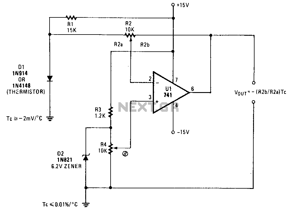
A simple operational amplifier and silicon diode form the core of a temperature-to-voltage converter, which allows the use of a standard voltmeter—either analog or digital—to measure temperature. User adjustments enable readings of either 10 mV or 100 mV to...

The multifunction frequency meter is an instrument that can measure various parameters on a single display using an 8-digit 7-segment LED. The controls measure... The multifunction frequency meter is designed to provide accurate measurements of frequency, voltage, current, and other...
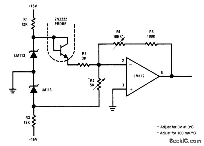
This simple circuit is an electronic thermometer that utilizes an inexpensive silicon transistor (2N2222) as the temperature sensor. The circuit provides an accuracy of better than 1°F over a 100°F range. An LM113 diode regulates the input voltage to...
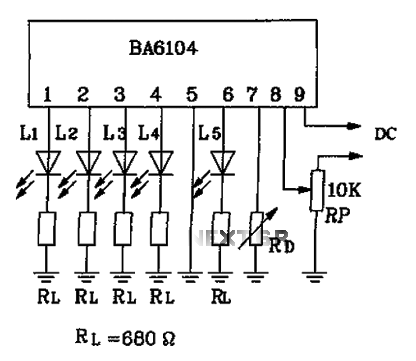
The BA6104 is a five-digit LED level meter driver integrated circuit (IC) used in basic application circuits. When the input level exceeds the required display threshold of 1V, only 7 feet of the power supply Vcc are indirectly affected...
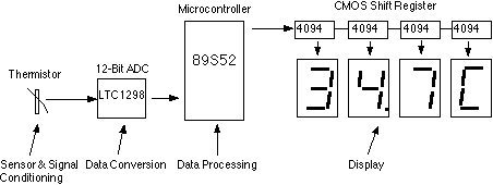
This assignment pertains to the course "Designing Microprocessor Based Instrumentation." The project features a board that utilizes a 12-bit ADC, a C program with digital filtering, and an LED display interface. It achieves a temperature reading sensitivity of 0.1°C....
To measure the frequency response of the e-meter, a Wien Bridge oscillator, oscilloscope, and single-ended power supply were used. The oscillator employs a TL074 quad op-amp, utilizing only two of the op-amps. Op-amps typically require two power supplies, one...