
555 Simple circuit diagram of the timing of time
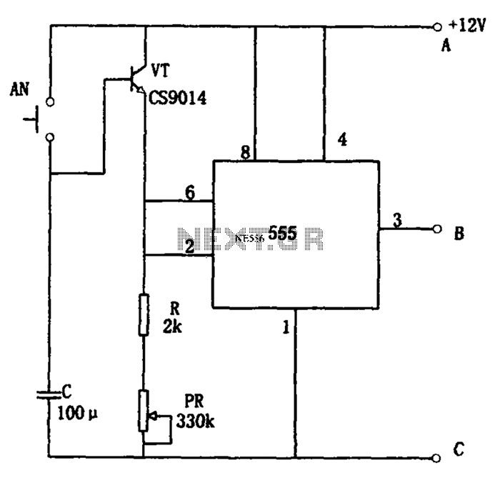
The described circuit employs a 555 timer IC configured in a monostable mode, which is fundamental for generating precise timing intervals. When switch AN is pressed, the 555 timer is triggered, starting the timing sequence. The timing duration is primarily determined by the resistor-capacitor (RC) network connected to the timer. The capacitor's value is crucial, as it dictates the length of the timing cycle; for instance, with a capacitance of 2200 µF, the circuit can achieve extended timing intervals, making it suitable for applications requiring long delays.
Adjustments to the timing can be made via the tone PR, which likely represents a variable resistor or potentiometer that alters the resistance in the RC circuit. This flexibility allows users to fine-tune the timing to their specific needs, ranging from short durations of 3 minutes to long durations up to 48 hours, depending on the capacitor's specifications.
The output from the 555 timer is a control signal that can drive a high-power control circuit. This circuit is capable of operating relays, which are essential for controlling larger loads that exceed the current ratings of the timer IC. The relays can be connected at various terminals (A, B, C) to manage different load types or configurations, allowing for versatile applications of the timing circuit.
In summary, this circuit provides a practical solution for timing applications, combining the reliability of the 555 timer with the flexibility of adjustable timing and the capability to control high-power devices through relay operation. This makes it suitable for various automation tasks, such as controlling lights, motors, or other electrical devices based on timed intervals. As shown for the long timing circuitry simple. Press the switch AN start timing, tone PR can alter timing, the timing range from 3 minutes to 220 minutes. If the capacitance C to 2200 F, the time range can be from 40 minutes to 48 hours. 555 pin output timing control signal. The use of the high power control circuit, will have in the B, C terminus or A, B termination relay. Relay contacts to control the various timings load.
Related Circuits
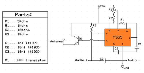
Planning to base a QRP transmitter on an instructables project, utilizing a large collection of 555 integrated circuits available. The issue is that this transmitter is designed to operate slightly below the commercial AM band. The goal is to...
This temperature controller utilizes an LM135/235/335 temperature sensor and is designed to maintain a small environment at a warm or hot temperature. A schematic diagram is provided. The temperature controller circuit is centered around the LM135/235/335 series of temperature sensors,...

Here is a design circuit for a frequency modulator that is equipped with a tuning circuit. In this circuit, a pair of 1N4007 diodes is utilized as varactor diodes. The choice of 1N4007 diodes is not due to their...
This circuit measures the distance covered during a walk. Hardware is located in a small box slipped in pants' pocket and the display is conceived in the following manner: the leftmost display D2 (the most significant digit) shows 0...

A South African company has developed a 5-kilowatt Fuel Free Generator and discovered that the longevity of the batteries is significantly affected by the process. There are various types of batteries available for testing, including different lead-acid batteries, gel...
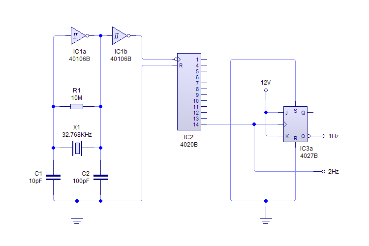
This plugin utilizes a quartz oscillator featuring a crystal (X1) to produce a 32,768 Hz (32,768 = 2^15) output. This frequency is fed into a 4020 14-Stage Ripple Counter, which divides the signal by 2^14, resulting in a 2...