
nicd battery charger using common electronic components
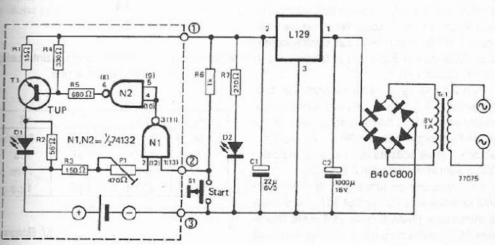
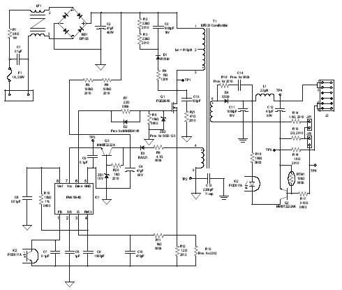
The circuit described operates as a battery charger with specific voltage and current regulation features. The maximum charge voltage of 1.45 volts is crucial for ensuring that the battery does not exceed its safe charging limit. The use of potentiometer P1 allows for fine-tuning of the charge voltage, accommodating variations in battery characteristics or user preferences.
The voltage divider comprising resistors R4 and R5 serves to produce a TTL-level control signal that manages the operation of the charging circuit. This signal is essential for the functioning of the Schmitt trigger, which provides hysteresis, ensuring stable operation during the charging process. The constant current source, established with transistor T1, is responsible for delivering a steady current of approximately 48 mA to the battery, facilitating efficient charging.
Diode D1 serves as an indicator for the charging status; its illumination signifies that the battery is actively being charged. Once the battery voltage reaches 1.15 volts, the Schmitt trigger's action causes D1 to turn off, indicating that the battery is fully charged and the charging process should cease to prevent overcharging.
The lower trigger threshold of 0.9 volts is a critical parameter, as it ensures that the charging cycle can only commence when the battery voltage is sufficiently low. The requirement to press switch S1 to initiate each charging cycle adds a layer of user control, preventing unintended charging.
For optimal performance with 1.2V/1500mAh batteries, the specified resistor values (R1 at 5.6 ohms and R2 at 12 ohms) and the choice of transistor (2N2904) are essential for achieving the desired charging current of 150 mA. These components must be selected and configured correctly to ensure reliable operation of the charging circuit. Overall, the design is tailored to provide a safe and efficient charging solution for compatible battery types.Since the maximum charge voltage measures 1. 45 volts and higher trigger threshold is about 1. 7 V, this voltage can be adjusted using potentiometer P1 to the value of 1. 45 volts. TTL control signal output by the voltage divider R4/R5, constant current source built with transistor T1, which provides a current of about 48mA. If D1 illuminates, it mea ns that the battery voltage is charged. If maximum load of 1. 15 volts is reached, the Schmitt trigger swings, D1 turns off (charging is completed). Since the lower trigger threshold is about 0. 9 volts, every charging cycle must be started by pushing S1 switch. For 1. 2v/1500mAh batteries which are charged with a current of 150mA, R1 must be 5. 6 ohms, R2 = 12 ohms, T1 = 2N2904. 🔗 External reference
Related Circuits
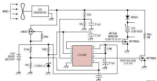
This simple wind charger circuit project is designed using the LTC1042 monolithic CMOS window comparator, manufactured by Linear Technology. The wind charger circuit utilizes wind power to generate the energy necessary for charging Ni-Cd or lead-acid batteries. When the...
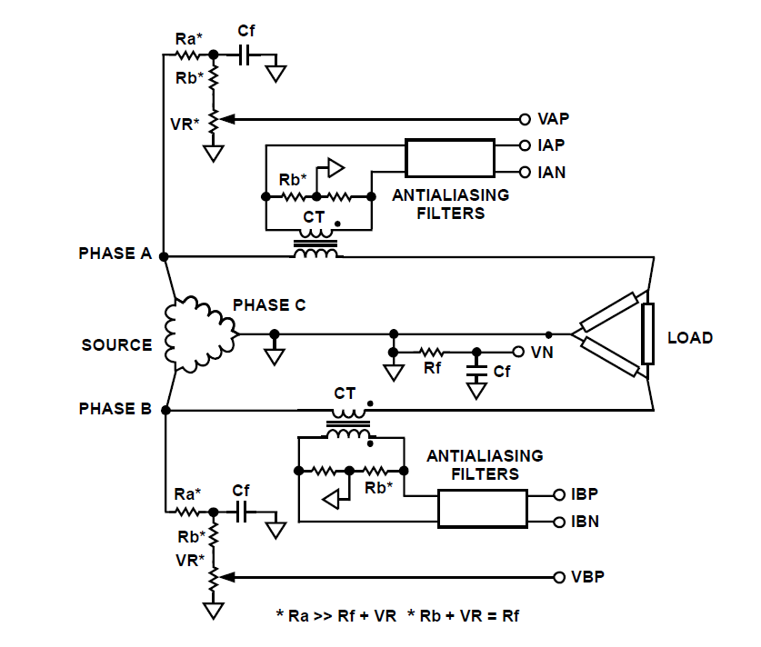
How can a circuit be built for digital readout of three-phase power consumption in a home using a chip like ADE7762? There is an interest in polyphase energy metering. To construct a circuit for digital readout of three-phase power consumption...
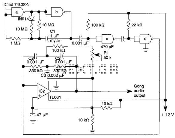
The electronic gong consists of an oscillator utilizing half of a 74C00 quad 2-input NAND gate, an active twin-T filter based on a TL081 operational amplifier, and an audio amplifier integrated circuit, such as the LM386N. Pulses generated by...
A high brightness LED evaluation board has been developed using the Fairchild Semiconductor FAN7554D PWM controller. The evaluation board for high brightness LEDs incorporates the Fairchild Semiconductor FAN7554D PWM controller, which is designed to provide efficient power management and precise...
I've always wanted to build an electronic LED dice, but something different from what we see on the internet. Making it motion controlled... now that's new! Many new cell phones that have accelerometers built in also have dice games....
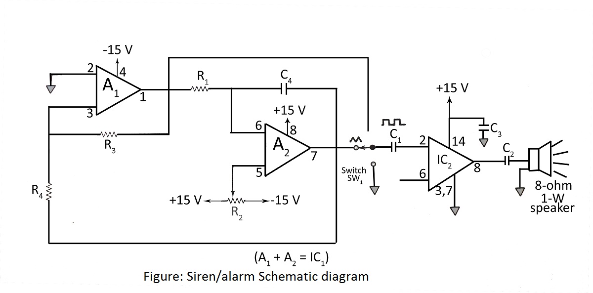
A simple siren or alarm circuit utilizing the MC1458 dual op-amp and the audio power amplifier LM380 is presented. The circuit diagram includes various configurations for sirens, doorbells, and alarm systems, along with a comprehensive parts list. The circuit operates...