
Vehicle Anti-Hijack Alarm No3 circuit

The described circuit functions as an advanced hijack alarm system, integrating both security and operational features to deter theft. The primary components of this system include a door switch, ignition switch, timer, siren, and the vehicle's engine control unit (ECU).
When the door switch is triggered while the ignition is on, it sends a signal to the timer circuit. The timer is programmed to initiate a delay—typically a few minutes. During this period, the system remains in a standby mode, monitoring for any further unauthorized access. If the vehicle is tampered with, the timer elapses, and the siren is activated, emitting a loud alarm to attract attention and deter the thief.
A critical distinction from earlier models is the engine's continuous operation. The circuit is designed to keep the engine running, preventing it from shutting down automatically. This feature is particularly advantageous, as it allows the vehicle to remain in motion, potentially aiding in the recovery of the stolen vehicle. The thief may find it challenging to navigate without turning off the ignition, as the system prevents any restart after the ignition is turned off.
The circuit design must ensure that the ignition switch is adequately integrated with the alarm system, allowing for seamless operation. Additionally, the siren must be selected based on its loudness and reliability in various environmental conditions.
In summary, this advanced hijack alarm system combines a delayed response mechanism with continuous engine operation to enhance vehicle security while providing a robust deterrent against theft. The careful integration of components ensures reliable performance under various conditions, making it an effective solution for vehicle protection.Like the first two Hijack Alarms - if a door is opened while the ignition is switched on - the circuit will trip. And after a few minutes delay - when the thief is at a safe distance - the Siren will sound. But this time the engine does not go on to fail automatically. Instead - it will continue to run until the thief turns off the ignition. Then the engine will not re-start.. 🔗 External reference
Related Circuits
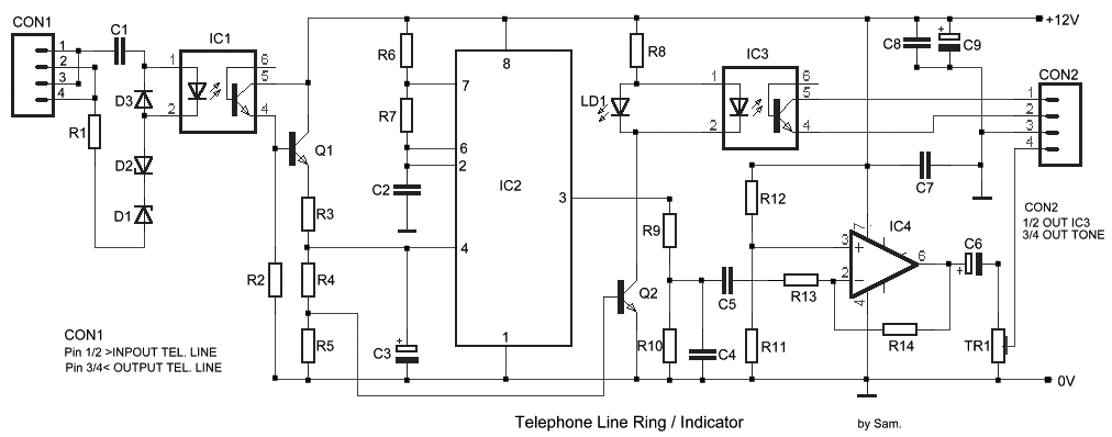
The circuit has been designed for telephone apparatus to indicate an incoming call as it rings using an LED for visual indication. BC550, an NPN general-purpose transistor, is utilized in the design. The circuit operates by detecting the ringing voltage...
The schematic illustrates a Simple Motorcycle Alarm Circuit Diagram created by Ron J. It incorporates micro-switches to safeguard removable panels and... The Simple Motorcycle Alarm Circuit Diagram is designed to enhance the security of motorcycles by utilizing a series of...
This circuit is designed for nighttime illumination and corridor lighting. During daylight, sufficient light causes BG3 to conduct, preventing the SCR from oscillating. As a result, the circuit remains inactive, and the light does not turn on. At night,...

R1 is a 15k ohm resistor. An NTC thermistor rated at 10k ohm, available at Radio Shack in the United States, is utilized. P1 is a 10k ohm potentiometer that sets the low speed (voltage) of the fans at...

The following circuit illustrates a Power Amplifier Circuit Diagram utilizing a 2N3055 transistor. Features include a 500-ohm current and an optimal voltage of 50V. The power amplifier circuit based on the 2N3055 transistor is designed to deliver significant output power,...
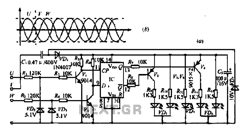
The three-phase voltage waveform diagram illustrates that when one phase voltage transitions from positive to negative across the zero point, the subsequent phase voltage becomes positive while the third phase remains negative. The U terminal voltage is positive when...