
Talking Yoda head
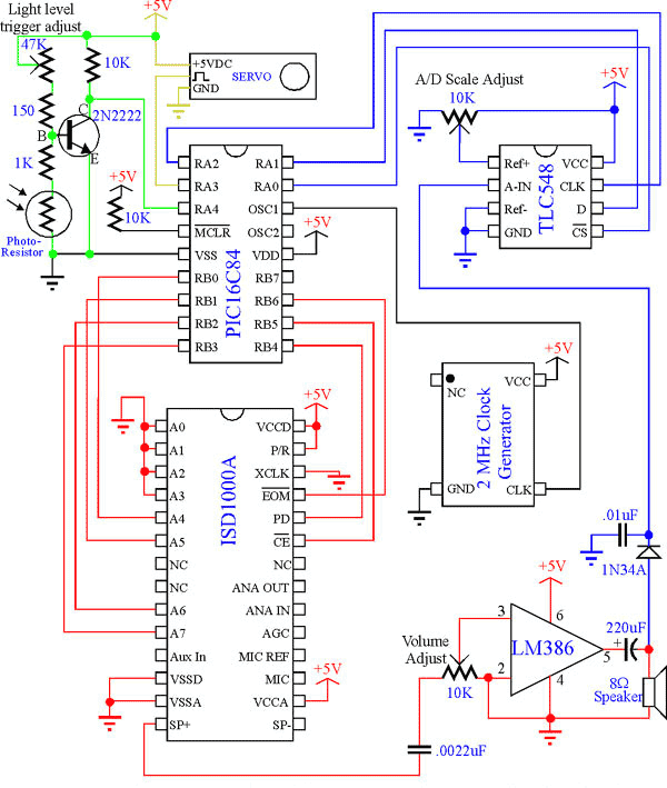
The project involves an interactive electronic system that utilizes a Yoda mask paired with a microcontroller to create a talking head effect. The system is designed to operate within a closed box, which serves as a trigger mechanism for audio playback. The light sensor, typically a Cadmium Sulfide photocell, detects when the box is opened due to the increased light exposure. This detection activates the microcontroller, which subsequently interfaces with the ISD1000A voice playback integrated circuit. The ISD1000A is programmed to play pre-recorded messages stored in its memory, with the ability to address these messages based on a simplified addressing scheme.
The audio output from the ISD1000A is routed to an Analog-to-Digital Converter (ADC), specifically the TLC548, which converts the audio signal into a digital format for further processing by the microcontroller. The microcontroller controls a servo motor to simulate mouth movements in sync with the audio playback, enhancing the realism of the talking head effect. The servo motor operates based on Pulse Width Modulation (PWM) signals generated by the microcontroller, allowing for precise control of the servo's position.
The circuit also includes a photosensor circuit that utilizes a 2N2222 transistor to manage the input signal to the PIC16C84 microcontroller. The variable resistor in the circuit allows for adjustment of the light sensitivity, ensuring reliable operation under varying lighting conditions. The system is designed for simplicity and efficiency, focusing on delivering an entertaining and engaging experience through the interaction of light detection, audio playback, and mechanical movement. Overall, the project exemplifies creativity in electronics, combining various components to achieve a cohesive and functional design.The talking Yoda head consists of a Yoda mask and a microcontroller system to achieve the desired operation/effect. The basic operation of the project was specified as follows: The head was to be placed inside a closed box.
Upon opening the box, the light sensor sends a signal to the microcontroller which, in turn, activates the ISD1000A to play message number one. The audio output is fed back into an A/D converter and processed in the microcontroller to make the mouth mechanics move via servo control.
When the box is closed again, message 2 is played. Upon reopening of the box, message 3 is played and then message 4 is continually played until the box is closed again. When the box is closed again, the system resets and prepares to play message 1 again when the box is reopened.
This project was born from a bad incident involving e-mail and Yoda. It was created as a practical joke for a fellow co-worker moving on to other aspirations. Because of a short time frame and eagerness by those involved, this project was completed in an amazing six days. These plans are not to be copied or distributed, in whole or in part, without the express written consent of one of the project contributors.
However, we give full permission to anyone that wishes to download and print out one, and only one, copy of these plans for personal use. No permissions are given, nor will be given, to anyone wishing to use these plans commercially. This project, nor the people involved, are in no way affiliated with Lucas Arts. This project was completely voluntary. The Analog-to-Digital converter used in this project is the TLC548. This is an 8-bit A/D converter which sends its data serially back to the microcontroller - one bit at a time.
The retrieval of a data sample is quite easy and only requires 3 data lines - two for control and one for data input to the microcontroller. To retrieve a data sample, the CS line of the A/D converter must be set low (this starts the data retrieval).
1.4 uS after the CS line goes low, the Most Significant Bit (MSB) of the 8-bit sample will appear on the data output pin of the A/D converter. To get the next 7 data bits, the CLK pin of the A/D converter must be set high (for at least 200 nS) and then set low (for at least 200 nS) for each bit.
Each bit will be sent out on the data output pin of the A/D converter during the low part of the CLK cycle. Below, Figure 2 details the sample retrieval process after the CS line of the A/D converter has been set low.
After the sample retrieval is complete, the CS line must be set high again and another cannot be retrieved for the next 17 uS. The ISD1000A is a voice record/playback I.C. that has the capacity of storing a total of 20 seconds of sound. The complete 20 second range is addressable and can hold more than one message. The addressing resolution is determined by the number of address bits used. If we used all 8 address lines, we would be able to address the storage range at 0.125 second intervals.
For our purposes, we used only the upper 4 address bits in order to conserve I/O lines on the microcontroller. This gave us a 2 second addressing resolution. Below, Figure 3 illustrates the mapping of the ISD1000As memory and how the 2 second addressing resolution affects message playback.
As you can see from Figure 3, example message 1 is about 5 seconds in length. Since we only have an addressing resolution of 2 seconds, we must then start example message 2 at the 6 second point in the memory map. A special case exists for any message that happens to play to the end of storage memory. When this happens, the ISD1000A locks up and needs to be reset by setting the PD input of the ISD1000A high and then back to low.
To play a message: First, the message address is set up and then the CE input of the ISD1000A is strobed low for at least 100 nS. When the message has finished playing, the end of message(EOM) pin goes low for 15.6 mS (unless the message played through the end of memory - in this case, the EOM pin stays low until the ISD1000A is reset).
Please note that the microcontroller circuit is only capable of playing messages; A separate circuit is required to initially store the messages in the ISD1000A. A simple recording schematic is included with the documentation of the ISD1000A if purchased from Radio Shack.
However, a simple recording circuit will be included here in the very near future. The type of servo described here is one commonly found in radio controlled vehicles. A servo is a motor in which the shaft does not continuously rotate. Instead, a servo’s shaft assumes a position based upon a Pulse Width Modulated (PWM) input. The PWM input is a positive-going pulse that has a width between 1 mS and 2 mS. This pulse must periodically occur once approximately every 20 with a pulse width of 1 mS, the servo shaft is at 0°. With a pulse width of 2 mS, the servo shaft rotates clockwise 90°. As the pulse width varies between 1 mS and 2 mS, so will the servo’s shaft position between the 0° and 90° positions.
Notice that there is a color code scheme throughout this project. The purpose of this is to provide a means of linking hardware to its related software and descriptions. The photosensor circuit operates in the following way: When light shines on the Cadmium Sulfide photocell, the resistance across the leads of the photocell decreases.
This decrease in resistance brings the base of the 2N2222 transistor "closer" to ground and, therefore, starts to turn off the transistor. If enough light illuminates the photocell, the transistor will shut off and the input pin to the PIC16C84 will be pulled "high" by the 10K resistor.
Otherwise, as long as the transistor is on, the input pin of the PIC16C84 will be pulled "low" through the collector-emitter junction of the transistor. The 47K ohm variable resistor is used to set the threshold level of the light detection circuit. The 150 ohm resistor is used to keep from frying the transistor in the event that the 47K ohm variable resistor is adjusted such that there is NO resistance across the 47K ohm variable resistor (the base of an NPN transistor is shorted to the emitter via a diode - if you were to put a regular diode in the forward bias position across a battery or power supply, you would see exactly what would happen to the transistor if the 150 ohm resistor was left out and the 47K ohm variable resistor was adjusted to "NO" resistance).
🔗 External reference
Related Circuits

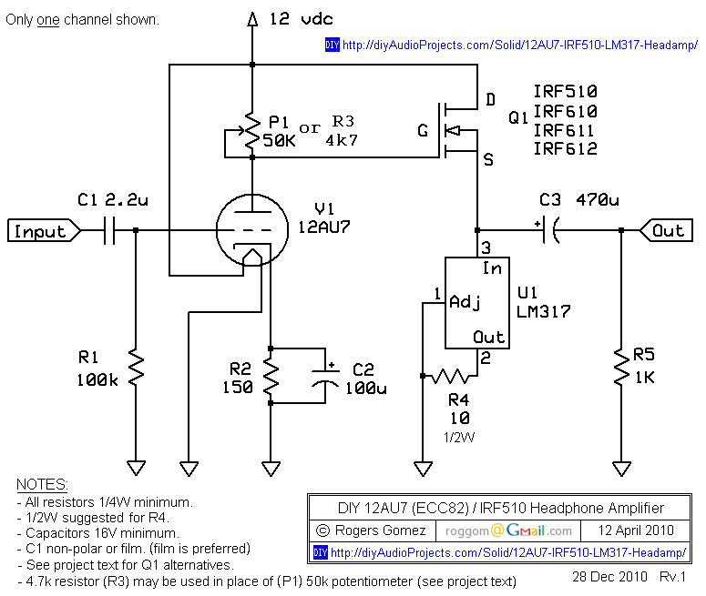
This is a simple headphone amplifier circuit designed to drive headphones when a music player lacks sufficient power. The circuit is straightforward and utilizes only three transistors. The first transistor, Q1 (BC 239), along with its associated components, functions...
Using this low cost project, one can reproduce audio from a TV without disturbing anyone. It does not use any wire between the TV and headphones. Instead of a pair of wires, it uses invisible infrared light to transmit...
The NP-100v12 is a straightforward headphone amplifier designed for entry-level builders to assemble and listen to their own creation. The term "builder" refers to individuals with electronic experience and innovation, allowing them to create a device rather than merely...
This circuit automatically activates and deactivates a motorcycle's headlight, functioning independently of both the light and ignition switches, as long as the battery is fully charged. The initial stage employs a 220-ohm resistor and ZD1 to keep transistor Q1...
When examining construction notes for building vintage detector-type radios, the specified headphones typically have an impedance of 2 G—2000. In contrast, modern headphones generally have a lower impedance of 2 G—32, which makes them unsuitable for such designs. However,...
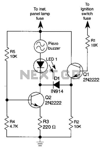
The base of Q1 is connected to the car's ignition circuit; the easiest point to make that connection is at the ignition switch fuse in the car's fuse panel. Also, one side of the piezoelectric buzzer is connected to...