
High voltage speed optocoupler and application circuit diagram
High-speed optocouplers are essential components in modern electronic systems, especially in applications requiring efficient isolation and signal transfer across different voltage domains. The rise time of less than or equal to 300 ns indicates the rapid response of these devices, making them suitable for high-frequency applications. The circuit transfer ratio of 50% signifies that the output signal strength is half of the input signal strength, which is adequate for many control and feedback applications.
The isolation voltage rating of at least 15,000 V ensures that the optocoupler can safely operate in high-voltage environments without risk of breakdown or signal interference between the high-voltage and low-voltage sides. The reverse breakdown voltage of at least 50 V for the output transistor further enhances the reliability of the optocoupler in circuits where transient voltages may occur.
In high-voltage regulator circuits, these optocouplers play a critical role by providing feedback from the output to the input circuit, allowing for precise regulation of voltage levels while maintaining electrical isolation. This isolation is crucial for protecting sensitive low-voltage components from high-voltage spikes or noise, thereby ensuring the integrity and stability of the entire system.
The requirement for a +27 V DC power supply on the high-pressure side, which must exceed 15 kV, indicates the need for careful design considerations in power management and safety measures. This independent power supply arrangement helps maintain the necessary voltage levels for proper operation while minimizing the risk of interference or damage to the low-voltage side of the circuit.
Overall, high-speed optocouplers are indispensable in applications where high-voltage isolation, rapid signal transfer, and reliable feedback mechanisms are necessary for the effective operation of electronic systems.High speed optocouplers technical parameters are: Rise time t1 ‰¤ 300ns; Circuit eye transfer ratio CTR = 50%; Isolation voltage VSO ‰¥ 15000V; Output transistor reverse breakdown voltage V (BR) CEO ‰¥ 50V. The optical coupler can be widely used for the high-voltage isolators, high-voltage pulse transformers and high-voltage power circuit voltage stability control system.
T he control systems is used for high voltage regulator circuit. The fast high-voltage electrical coupling in this circuit play two roles. First one is to achieve the output voltage feedback loop in the input circuit and high voltage isolation between the low-voltage circuits; The other role is to achieve high output voltage feedback signal. Note: The high pressure side +27 V DC power supply is independent, but its pressure level must be greater than 15KV.
🔗 External reference
Related Circuits
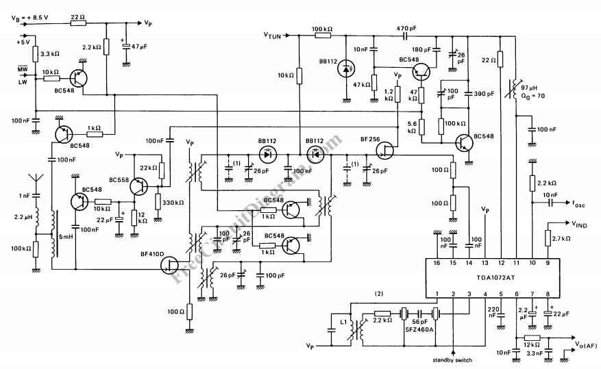
The TDA1072AT is a specialized integrated circuit designed for AM radio receivers, produced by Philips Semiconductors. This IC is intended for use in both mains-fed home receivers and car radios. It features a voltage-controlled oscillator that delivers signals with...
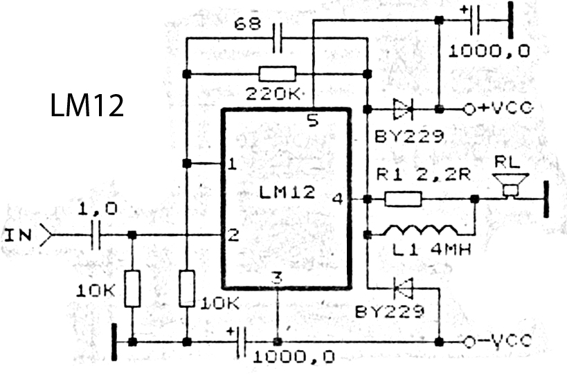
This is an amplifier circuit utilizing the LM12 integrated circuit as the primary amplifier. The amplifier delivers a power output of 150 watts and operates with a load impedance of 4 ohms. It is classified as a high-output power...

This second-order filter, designed for audio applications, utilizes an LM1458 or a similar operational amplifier. It is tunable with a cutoff frequency ranging from 30 Hz to 300 Hz. The resistors R2a and R2b are ganged log-taper potentiometers. The described...
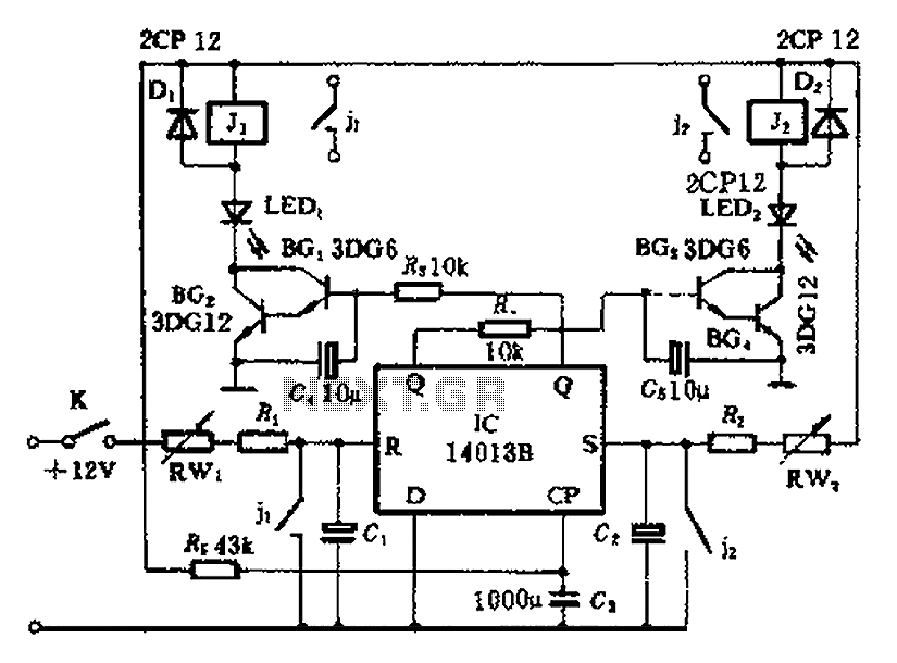
The timing control circuit is a sequential circuit that allows for sequential timed control of two switches. The control time can be adjusted from a few seconds to several tens of seconds. If mechanical control is applied for reciprocating...
The frequency of a crystal-controlled oscillator is maintained with high precision through the use of a quartz crystal. The frequency is primarily determined by the dimensions of the crystal, particularly its thickness, while other circuit parameters have minimal impact....

The circuit depicted here is designed to identify defective bulbs by capacitively sensing the electric fields they generate. To understand its operation, consider a string of bulbs with an open-circuited filament, referred to in the schematic as the String...
Warning: include(partials/cookie-banner.php): Failed to open stream: Permission denied in /var/www/html/nextgr/view-circuit.php on line 713
Warning: include(): Failed opening 'partials/cookie-banner.php' for inclusion (include_path='.:/usr/share/php') in /var/www/html/nextgr/view-circuit.php on line 713