
TDA2030 18W + 18W Stereo Hi-Fi Audio Amplifier circuit and explanation
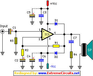
The 2 x 18W Hi-Fi Stereo Power Amplifier circuit utilizes the TDA2030 IC, which is renowned for its performance in audio amplification applications. The TDA2030 operates efficiently in a range of configurations, making it suitable for both home audio systems and small public address systems. Its low total harmonic distortion (THD) ensures high fidelity sound reproduction, which is critical in high-quality audio applications.
The amplifier's design emphasizes stability and reliability, featuring built-in protection mechanisms that guard against overload conditions and short circuits at the output. This is particularly important in scenarios where the amplifier may be subjected to varying loads or unexpected signal spikes, ensuring that the integrity of the connected speakers is maintained.
Power requirements for this amplifier are specified at ±18Vdc with a current capacity of 3A, necessitating a dual power supply arrangement. This symmetrical power supply configuration is essential for the proper functioning of the amplifier, as it allows the output signal to swing positively and negatively around a central ground reference, which is crucial for balanced audio output.
The circuit's compatibility with 4 and 8 Ohm loads broadens its applicability, allowing it to drive a variety of speaker configurations. The inclusion of a large heat sink is vital, as the TDA2030 can generate significant heat during operation, especially under high load conditions. Proper thermal management ensures that the amplifier operates within safe temperature limits, enhancing its longevity and performance.
For stereo operation, it is necessary to construct two identical circuits, one for each channel. The schematic diagram provided typically represents only one channel (left), and duplicating this setup will yield a complete stereo amplifier capable of delivering rich and immersive sound experiences.
Overall, this amplifier design is suitable for enthusiasts looking to enhance their audio systems with a reliable and efficient power amplification solution.2 x 18W Hi-Fi Stereo Power Amplifier based around two TDA2030 ICs. It has good input sensitivity, low distortion, good operating stability and full protection against overloads and output short-circuits. It can be used as a booster amplifier for existing small systems or to drive a second pair of speakers besides the ones already connected to the
system. The board needs a symmetrical power supply of ±18Vdc/3A and can be connected to loads of 8 or 4 Ohm. Large heat sink is required for this circuit. Diagram shown below indicates only left channel. Make two circuits for for stereo version. Disclaimer All files are found using legitimate search engine techniques. This site does not and will not condone hacking into sites to create the links it list. We will and do assume that all links found on the search engines we use are obtained in a legal manner and the webmasters are aware of the links listed on the search engines. If you find a URL that belongs to you, and you did not realize that it was "open to the public", please use the report button to notify the blogmaster of your request to remove it or it will remove within 24 hours.
This is not an invitation for webblog haters to spam with requests to remove content they feel that is objectionable and or unacceptable. Proof of URL ownership is required. NOTICE: This Blog Has Already Been Reviewed And Accepted By Blogger. com 🔗 External reference
Related Circuits
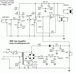
The following diagram represents a 20W power amplifier circuit constructed using the EL34 tube component. The EL34 is a well-known tube that is highly regarded for use in power tube amplifiers. The circuit includes both the tube amplifier schematic...
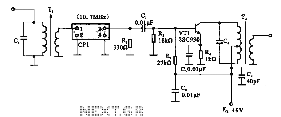
This circuit features a ceramic filter integrated with an FM intermediate frequency (IF) amplifier. The FM IF amplifier circuit primarily consists of an input variable voltage regulator (T), ceramic filters (CF1), and additional components such as the IF amplifier...
The frequency range for the FM transmission band is 90 MHz (megahertz, or 90 million cycles per second). Due to the variable tuned circuit in the FM transmitter, it can be tuned to a specific frequency within the local...
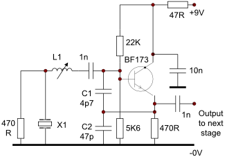
This circuit operates effectively from low frequencies up to at least 120 MHz using series resonant crystals in their fundamental or overtone mode. The output can be obtained from the feedback tap, a low impedance winding on L2, or...
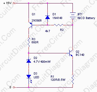
In appliances that require alternating current, NiCad (NiCd) rechargeable batteries still demonstrate significant performance advantages compared to NiMH and lithium batteries. The charger circuit is critical in handling incorrect polarity of the battery placement. The core of this battery...
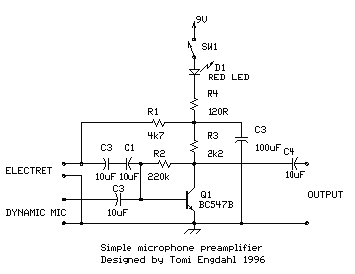
This is a simple microphone preamplifier circuit designed for use between a microphone and a stereo amplifier. This circuit is compatible with standard home stereo amplifier line, CD, aux, and tape inputs. It can accept both dynamic and electret...
Warning: include(partials/cookie-banner.php): Failed to open stream: Permission denied in /var/www/html/nextgr/view-circuit.php on line 713
Warning: include(): Failed opening 'partials/cookie-banner.php' for inclusion (include_path='.:/usr/share/php') in /var/www/html/nextgr/view-circuit.php on line 713