
TDA3567 Ntsc Decoder

The TDA3592A is a versatile transcoder integrated circuit designed to facilitate the conversion of SECAM video signals into PAL format. This functionality is crucial for applications that require compatibility with PAL-based systems, which are widely used in various broadcasting environments. The device operates by processing the SECAM input signals and accurately generating corresponding PAL output signals, ensuring minimal loss of quality during the conversion process.
The TDA3592A features a range of input and output configurations, allowing it to interface seamlessly with different types of PAL decoders. This flexibility makes it suitable for integration into a variety of television and multimedia systems. The circuit utilizes advanced signal processing techniques to handle the color encoding and decoding processes inherent in SECAM and PAL formats, ensuring that color fidelity and image integrity are maintained throughout the transcoding operation.
In addition to its primary function as a transcoder, the TDA3592A may include features such as automatic gain control, which helps to stabilize output levels, and noise reduction capabilities that enhance the overall quality of the video signal. The device is designed for ease of integration, with a straightforward pin configuration that simplifies connections to other components in the system.
Overall, the TDA3592A transcoder circuit is an essential component for systems that require the conversion of SECAM signals to PAL, providing reliable performance and compatibility with a wide range of PAL decoders. Its design reflects NXP Semiconductors' commitment to delivering high-quality solutions for video signal processing.The TDA3592A transcoder circuit converts SECAM input signals into true PAL signals, and CAN be used in combination with all types of PAL decoder By NXP Semiconductors 🔗 External reference
Related Circuits
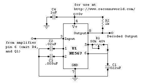
This circuit is designed to trigger on a 1 kHz tone. To change this frequency, refer to the table below, then change the resistor and capacitor values accordingly. More: all resistors are 5 or 10 percent tolerance, 1/4-watt; all...
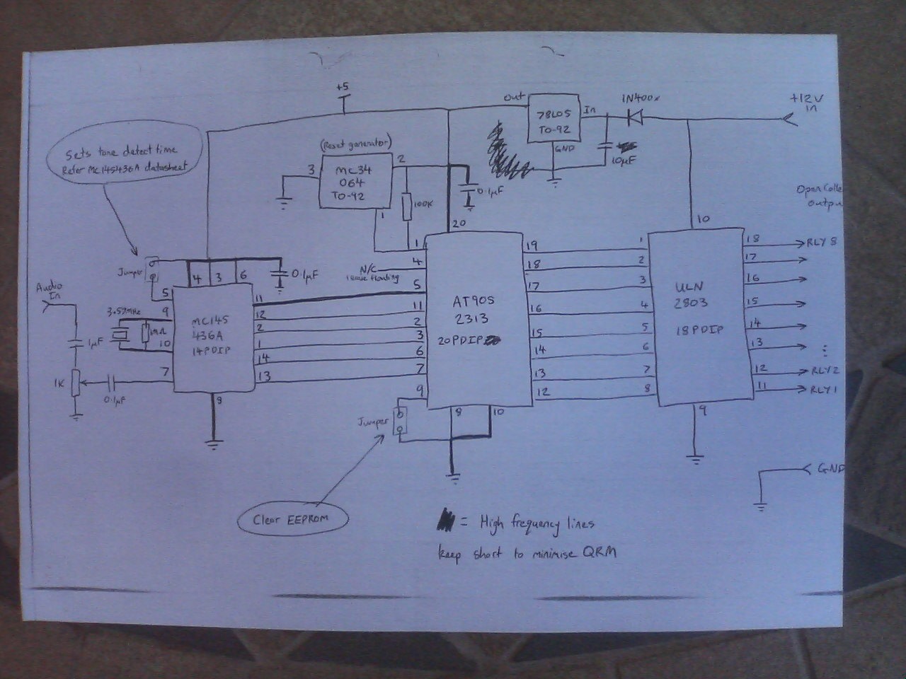
After a power interruption, all relays revert to their previous states, which are stored in non-volatile memory. A Motorola MC145436 DTMF decoder is utilized, clocked by a 3.58 MHz NTSC color burst crystal, providing a divide-by-8 clock output of...
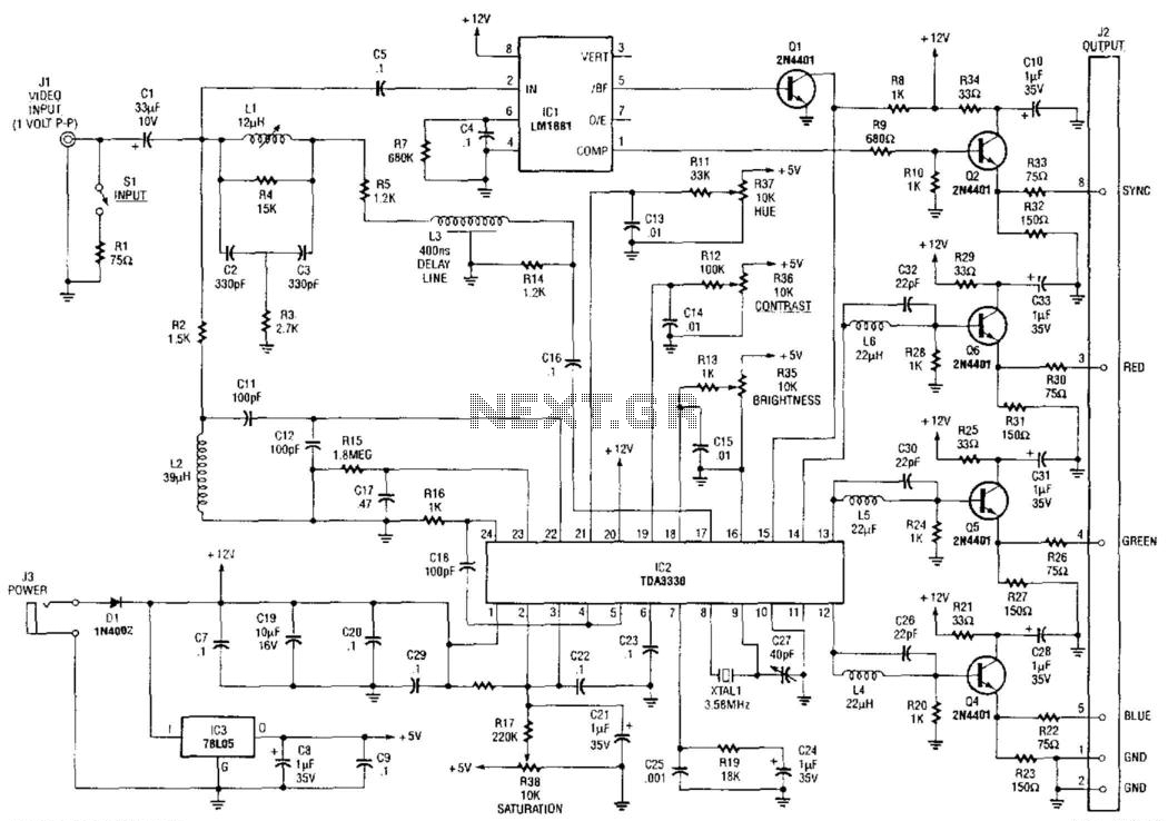
An NTSC/RGB decoder is presented here. Utilizing a TDA3330, a 1-V input video signal is decomposed into its red (R), green (G), and blue (B) components, along with composite sync. U1 serves as an integrated sync separator (LM1881). This...
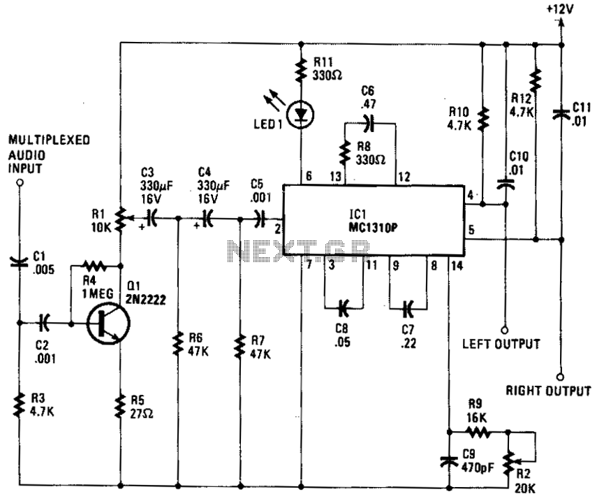
The composite input signal is amplified by transistor Q1 and is then connected to a high-pass filter consisting of capacitors C3 and C4, along with resistors R6 and R7. The filtered audio signal is subsequently sent to IC1, which...
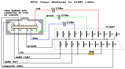
The schematic diagram is similar to the SNES NTSC RGB cable, with the only modification being the addition of capacitors to the RGB line. The diagram is accurate, but it does not include capacitors. A GameCube SCART lead can...
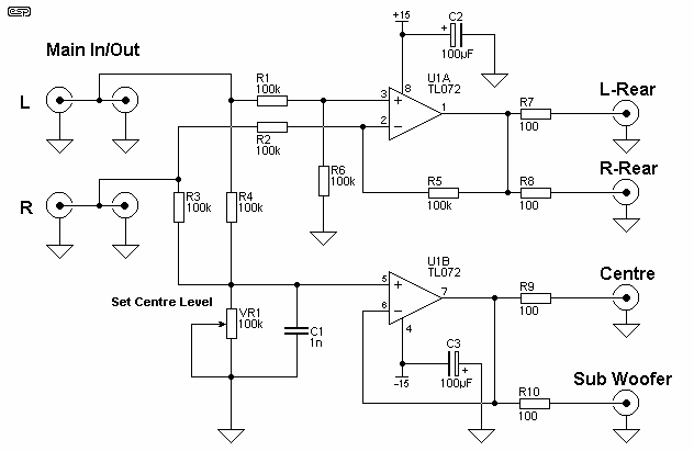
This surround-sound decoder is based on the "Hafler" principle, first discovered by David Hafler in the early 1970s. The original idea was to connect a pair of speakers for use as rear speakers in a surround setup. While this...