
Schematic diagram for the One Transistor FM Radio with Improved Audio Gain
To implement the described circuit modifications, the variable capacitor (C3) must be configured in a series arrangement to enhance tuning linearity. This configuration utilizes the outer terminals of C3, effectively bypassing the central lead to provide a more stable tuning range. The gain achieved through this setup is adequate for driving standard earphones; however, users situated at a considerable distance from broadcasting stations may experience challenges in audio clarity and volume.
The absence of an external antenna option presents limitations in reception capabilities. An external antenna would necessitate the integration of an additional transistor to amplify the incoming signal. For users seeking to improve audio performance, especially in cases where the TL431CLP chip is not accessible, alternative audio amplification solutions are recommended. The LM386 and TDA7052 amplifiers are both viable substitutes that can be integrated into the design.
In the case of the TDA7052, the Quasar DIY project kit #3027 serves as a comprehensive solution, offering all necessary components for assembly. This kit is particularly suitable for users who require a straightforward application of the TDA7052 amplifier, ensuring compatibility and ease of use within the existing circuit framework. The integration of these components will enhance audio output, making the overall system more effective for various listening environments.Connect the two sections of the variable capacitor (C3) in series to linearize the tuning somewhat. That is, use the connections on either end of C3 and don`t use the middle lead. The gain is just enough to drive an earphone. If you live too far away from radio stations, you might have trouble hearing one. There is no option here for an external a ntenna (that would require and extra transistor). If you want a little more audio gain, or you cannot locate a TL431CLP chip, you can use some other audio amplifier in the circuit where pins 1 and 2 of D1 normally connect. You can use an LM386 or a TDA7052 audio amplifier. Quasar DIY project kit #3027 is a complete TDA7052 audio amplifier kit and it works fine in this application.
🔗 External reference
Related Circuits
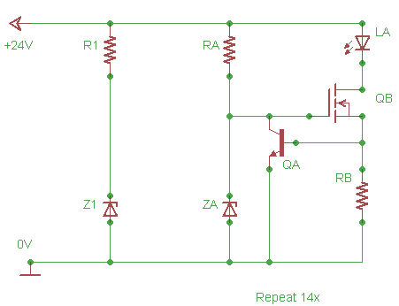
Design a lighting circuit for an indoor garden. There is a 24V input source that needs to be limited to 20V. LA is a series array of LEDs with a total voltage drop of approximately 19.8V. R1 and Z1...
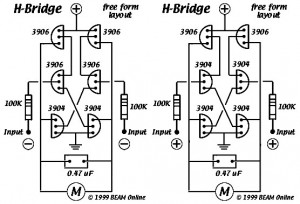
This diagram illustrates the 6-transistor Tilden H-bridge circuit. While it is not as old as the original basic H-bridge, it has a significant history and serves as the foundation for many BEAM driver circuits. Revised drawings were created for...
This is a transistor inverter circuit diagram rated for 100 watts, designed as an easy-to-build circuit. It utilizes only transistors and does not incorporate any integrated circuits. The circuit converts a 12V battery input to a 220V, 50Hz square...
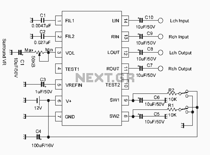
The NJM2701 3D surround sound audio processor integrated circuit can be designed into a very simple 3D surround sound system. The NJM2701 reproduces 3D surround sound using only two speakers and is suitable for various audio applications, including micro-components,...
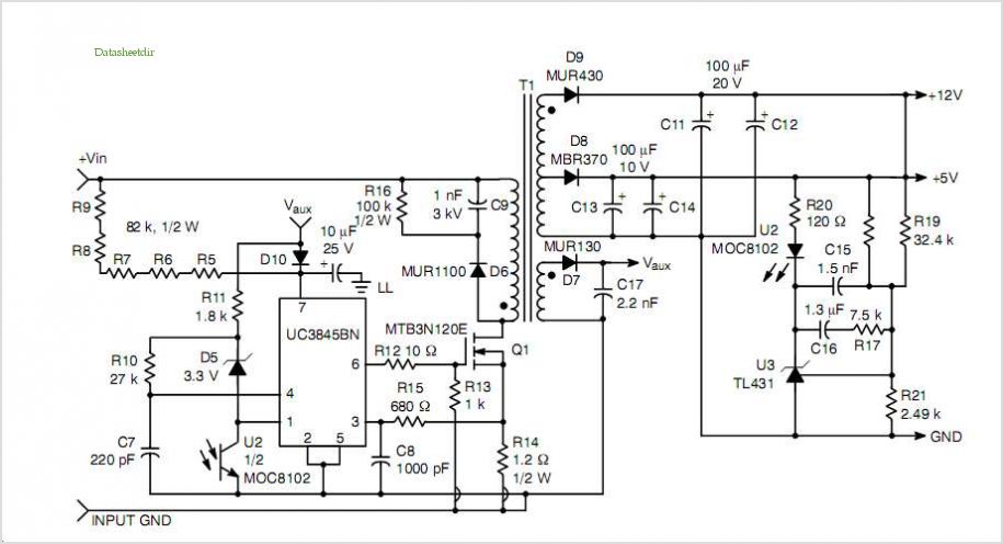
This post summarizes the work of experts in switching power supply schematic diagrams who are thoroughly knowledgeable about all aspects of the subject. Switching power supplies are crucial components in modern electronic devices, providing efficient voltage regulation and power conversion....
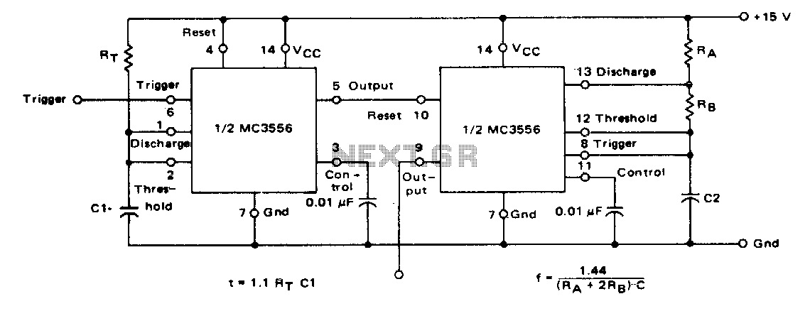
The first timer is used as a monostable and determines the tone duration when triggered by a positive pulse at pin 6. The second timer is enabled by the high output of the monostable. It is connected as an...
Warning: include(partials/cookie-banner.php): Failed to open stream: Permission denied in /var/www/html/nextgr/view-circuit.php on line 713
Warning: include(): Failed opening 'partials/cookie-banner.php' for inclusion (include_path='.:/usr/share/php') in /var/www/html/nextgr/view-circuit.php on line 713