
Telephone Bell Simulator Circuit
This circuit is structured to generate a specific ringing tone for private telephone systems, ensuring a clear and recognizable signal for incoming calls. The oscillator, formed by components N1 and N2, operates at a frequency of 5 Hz, allowing it to produce a periodic signal with a total cycle time of 200 ms. This cycle is essential to create the desired ringing sequence, which is characterized by alternating periods of tone and silence.
The oscillator output is fed into two decade scalers, N3 and N4, which serve to reduce the frequency of the incoming signal. The configuration of these scalers is crucial as they work together to divide the frequency by 15, resulting in the appropriate timing for the ringing sequence. The use of decade scalers allows for precise control over the frequency division, making it possible to achieve the required ringing intervals.
The second input of N4 is an optional feature that allows for the divider to be activated or deactivated based on logic levels. This capability provides flexibility in the circuit's operation, allowing it to be integrated into systems where the ringing function may need to be controlled dynamically. If this optional feature is not implemented, it is necessary to connect the two inputs of N4 together to ensure proper operation of the circuit.
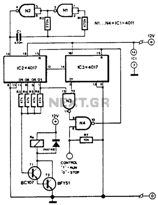
Overall, this telephone ringing circuit is designed for reliability and ease of integration into existing telephone systems, providing a simple yet effective solution for generating a distinct ringing tone. This circuit is intended for use in a small private telephone installation. The ringing tone sequence is 400 ms on, 200 ms off, 400 ms on, 2 ms off. In the accompanying diagram, N1 and N2 form an oscillator that operates at a frequency of 5 Hz, which gives a period of 200 ms. The oscillator signal is fed to two decade scalers, which are connected in such a manner (by N3 and N4) that the input signal is divided by 15.
The second input of N4 can be used to switch the divider on and off by logic levels. If this facility is not-used, the two inputs of N4 should be interconnected. 🔗 External reference
Related Circuits
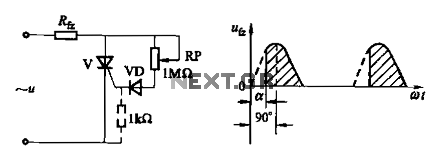
Figure 16-3 (a) illustrates a one-way thyristor, while Figure 16-3 (c) depicts a triac. The circuit characteristics indicate a simple phase shift range of 90 degrees for the thyristor and 180 degrees for the triac. These components are influenced...
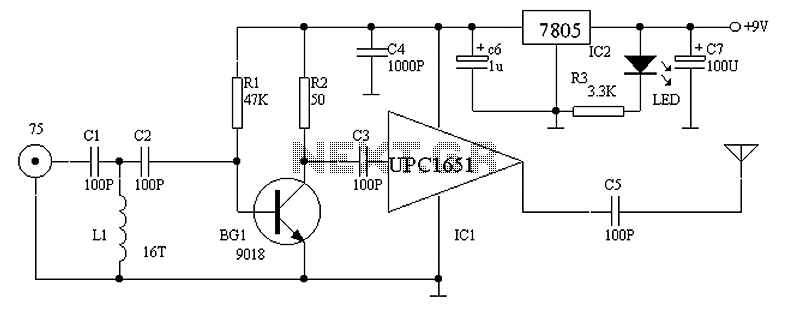
Circuit Overview Many families now own various electronic devices such as televisions, VCD players, video recorders, game consoles, cameras, and DVDs. This circuit involves an RF signal repeater designed to work with a television signal transmitter, covering a radius...
This stereo noise blanker or suppressor attenuates noise by 45 dB when the music signal is low or absent; it functions primarily as a noise limiter. The noise blanker sensitivity... This circuit serves as a stereo noise blanker or suppressor,...
Many battery-powered devices use two AA alkaline cells. Often, it is not apparent when it is time to replace the batteries until the device powered by them ceases to function. In battery-powered devices that utilize two AA alkaline cells, it...
In this circuit, two 567 tone decoders are utilized. One functions as an oscillator, while the other acts as a detector. Connecting TP1 and TP2 allows U2 to receive the signal from U1, resulting in pin 8 of U2...
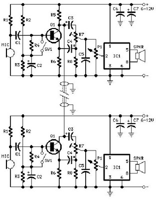
A project is proposed to construct a two-phone intercom system capable of functioning over a distance of up to 1 kilometer. The system will utilize the speaker of each phone to produce a ringing sound on the other end. The...