
Telephone Hold Circuit Circuit
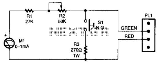
The described circuit utilizes a silicon-controlled rectifier (SCR) to control the connection between an LED and a resistor across a telephone line. When the switch SI is engaged, the SCR is triggered into a conductive state. This allows current to flow through LED1 and resistor R1, which are connected in parallel to the telephone line.
The activation of the SCR results in a significant voltage drop across the line, stabilizing at around 20 volts. This voltage level is critical as it ensures that the necessary signaling and communication with the telephone company's central office is maintained. The LED serves as an indicator that the circuit is active, while resistor R1 limits the current to prevent damage to the components.
In practical applications, this configuration can be used in various telecommunication systems where visual indication of line status is required. The use of an SCR allows for efficient control of the circuit, ensuring that the LED lights up only when the switch is pressed, thus providing a clear visual cue while maintaining the integrity of the telephone line connection. Additionally, careful selection of R1 is essential to ensure proper current flow through the LED without exceeding its rated specifications. When SI is pressed, the SCR fires, and places LED1 and Rl across the phone line. The line voltage drops to about 20 V, which holds the connection to the phone company`s central office. 🔗 External reference
Related Circuits
White Light Emitting Diodes (LEDs) now available can serve as a strong alternative to incandescent lamps in lighting applications. Today's White LEDs are... White Light Emitting Diodes (LEDs) represent a significant advancement in lighting technology, offering energy efficiency, longevity, and...

The circuit described below is notable for its low power consumption. With a 9V input and no load at the output, it draws only 50 mA, which is significantly lower than the quiescent current of a 78L05 regulator. The...
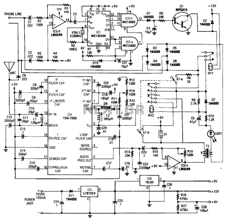
When the asterisk (*) is pressed on the touch-tone phone, a DTMF decoder, referred to as TCI, manages the on-hold logic. Audio from the FM receiver IC4 is transmitted over the telephone line when a hold condition is active....
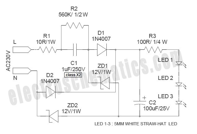
The circuit below illustrates powering one or two LEDs from the 120-volt AC line using a capacitor to drop the voltage and a small resistor to limit the inrush current. Since the capacitor must pass current in both directions,...
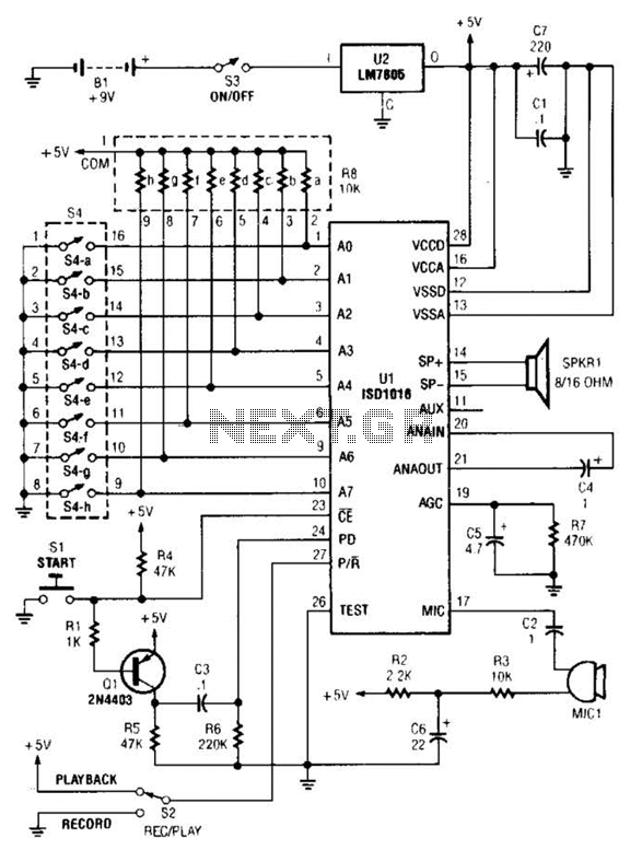
The personal message recorder is based on the ISD1016 CMOS voice messaging system, eliminating the need for complex and costly analog-to-digital and digital-to-analog conversion circuits. A functional block diagram of the ISD1016 is available. The ISD1016 integrates all necessary...
Electronics tutorial on combinational logic circuits that utilize logic gates to create multiplexers, encoders, and solid-state switches. Combinational logic circuits are fundamental components in digital electronics, characterized by their ability to produce outputs based solely on the current inputs, without...
Warning: include(partials/cookie-banner.php): Failed to open stream: Permission denied in /var/www/html/nextgr/view-circuit.php on line 713
Warning: include(): Failed opening 'partials/cookie-banner.php' for inclusion (include_path='.:/usr/share/php') in /var/www/html/nextgr/view-circuit.php on line 713